2D Profile reference
Used for programming 2 axis machines without rotary tools. This includes WaterJet, Plasma, Laser and Wire EDM machining.
Manufacture > Fabrication > Cutting > 2D Profile ![]()
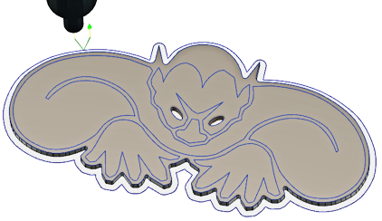
The 2D Profile (formerly Waterjet) toolpath is used for programming machines without rotary tools. The spindle axis cuts the part with a stream of abrasive water, or heat, in the form of a Laser or a Plasma torch. Typically this is a 2 axis contour on a sheet of material. But the material might be anything from thin sheet metal, to stone or ceramic.
Laser Cutting: A thermal process for cutting, that severs metal by melting or vaporizing with the heat from a laser beam. The process is used with or without gas to assist in the removal of molten and vaporized material. Can also be used for etching. Most accurate. Smallest Kerf width.
Waterjet Cutting: Severs metals and other materials using a high-velocity, high pressure stream of water, with an abrasive added to the water jet stream. The jet is formed by forcing water through a small diameter orifice under high pressure [30 000 to 60 000 psi]). At these pressures, the water erodes many materials rapidly, acting like a saw blade. Can also be used for etching. Good accuracy. Moderate Kerf width.
Plasma Cutting: The process to sever electrically conductive materials as a result of the electrical heating of any gas to a very high temperature so that its atoms are ionized. The plasma gas flows through a chamber, is heated and ionized by an electric current. This current runs between the electrode and the nozzle, or the work piece. Least accurate. Largest Kerf width.
 Tool tab settings
Tool
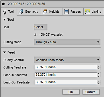
Select an appropriate tool from the tool library.
![]()
Use the Filter function limit the type of tools being displayed.
![]()
Use the "New Waterjet/Plasma/Laser" icon to create a tool. The type of Tool/Nozzle you select will effect some of the toolpath options.
Cutting Mode
Changes the cutting output parameters depending then the machine type and the selected postprocessor. Use this for machines that have internal "Quality" tables to determine the appropriate cutting feeds based on the material being cut. Etch and Vaporize also change the cutting quality. Some of these terms may apply to specific machine manufacturers settings. These modes will not be available for all machines, and so the post processor may issue an error and fail.
- Through - auto - The postprocessor has more control with this option and may change the settings based on the size of the contour (area, perimeter) or other information embedded in special parameters in the toolpath. This is the default setting.
- Through - high quality - Cuts through the material with the highest quality cut, but may be the slowest.
- Through - medium quality - Cuts through the material with an intermediate quality cut.
- Through - low quality - Cuts through the material with the lowest quality cut, but may be the fastest.
- Etch - Makes a visible mark on the surface without cutting through, by controlling the power of the jet as well as the feedrate. With this option, the geometry is the centerline of the toolpath with no cutter width compensation.
- Vaporize - This option is often used in laser cutting to remove the plastic coating commonly found on stainless steel. The coating is first vaporized using an operation with specific laser settings, and then a second operation cuts the material.
Quality Control
This drop-down menu setting determines whether the feedrates are controlled by the program or by the machine, thru the post processor.
Machine Uses Feeds changes the output to the feedrate selected by the user. Machine Uses Quality changes the output to access the machines feedrate calculation tables. Some machines use internal tables determines feedrates based on the required quality of the finish (Cutting Mode), material thickness and material type.
- Machine uses feeds - The feedrates are set on the Tool tab by the user.
- Machine uses quality - Changes the output to access the machines feedrate calculation tables. Some machines use internal tables to determine the cutting speed based on the required quality of the finish (Cutting Mode), material thickness and material type.
Cutting Feedrate
Feed used in cutting moves.
Lead-In Feedrate
Feed used when leading in to a cutting move.
Lead-Out Feedrate
Feed used when leading out from a cutting move.
 Geometry tab settings
Contour Selections
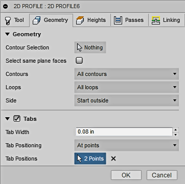
Click this button to select the contour profile(s) or Faces. Contiguous edges are automatically chained. If you select a Face, you can use the Loop options below to filter Inner or Outer loops selections. You can also select Sketches directly from the Browser Tree.
Contours
Use this Filter to select Open or Closed contours from a Face selection.
- All contours - Select All contours from the selected face
- Open contours - Select only Open contours from the selected face
- Closed contours - Select only Closed contours from the selected face
Loops
If a Face is selected, you can sort which loops you want to machine.
- All loops selected - Both Inner and Outer Loop boundaries will be selected.
- Outer loops selected - All Outer Loop boundaries will be selected.
- Inner loops selected - All Inner Loop boundaries will be selected.
Side
Use this to offset the contour inside or outside from the original edge or sketch geometry. Can be used to Etch along the edge of a profile. Allows you to shift from the selected Sideways Compensation direction or reverse the compensation offset direction.
If the Tool - Cutting Mode is set to Etch, Sideways Compensation will default to Center. Changing the '''Side''' options will not work unless Sideways Compensation is set to Left or Right
Tabs
Tabs are used to keep the part secured to the sheet until all the machining processes are finished. In many cases a small tab can be snapped off simply by shaking the finished sheet. The number and size of the tabs you use, will depend on the type and thickness of the material you are machining. When machining inside contours, a tab can keep the slug from tipping up and damaging the machines cutting nozzle.
- Tab Width - The width of the tab you want to create.
- Tab Positioning -
- By distance You can specify the distance between tabs with an explicit numeric value.
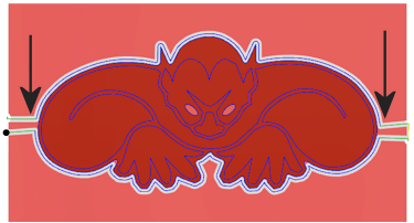
- At points You can pick points along the contour path to indicate the desired tab positions.
- Tab Distance - Specify a distance value if By distance is selected.
 |
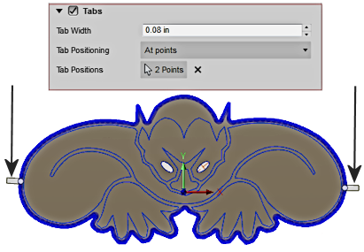 |
| At Points lets you select as many tab locations as you like. | The Simulated toolpath shows the remaining Tabs. |
 Heights tab settings
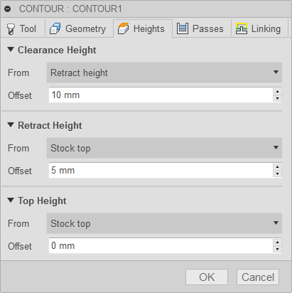
Clearance Height
The Clearance height is the first height the tool rapids to on its way to the start of the tool path.
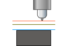 Clearance Height
- Retract height: incremental offset from the Retract Height.
- Top height: incremental offset from the Top Height.
- Model top: incremental offset from the Model Top.
- Model bottom: incremental offset from the Model Bottom.
- Stock top: incremental offset from the Stock Top.
- Stock bottom: incremental offset from the Stock Bottom.
- Selected contour(s): incremental offset from a Contour selected on the model.
- Selection: incremental offset from a Point (vertex), Edge or Face selected on the model.
- Origin (absolute): absolute offset from the Origin that is defined in either the Setup or in Tool Orientation within the specific operation.
Clearance Height Offset
The Clearance Height Offset is applied and is relative to the Clearance height selection in the above drop-down list.
Retract Height
Retract height sets the height that the tool moves up to before the next cutting pass. Retract height should be set above the Feed height and Top. Retract height is used together with the subsequent offset to establish the height.
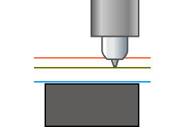
Retract Height
- Clearance height: incremental offset from the Clearance Height.
- Top height: incremental offset from the Top Height.
- Model top: incremental offset from the Model Top.
- Model bottom: incremental offset from the Model Bottom.
- Stock top: incremental offset from the Stock Top.
- Stock bottom: incremental offset from the Stock Bottom.
- Selected contour(s): incremental offset from a Contour selected on the model.
- Selection: incremental offset from a Point (vertex), Edge or Face selected on the model.
- Origin (absolute): absolute offset from the Origin that is defined in either the Setup or in Tool Orientation within the specific operation.
Retract Height Offset
Retract Height Offset is applied and is relative to the Retract height selection in the above drop-down list.
Top Height
Top height sets the height that describes the top of the cut. Top height should be set above the Bottom. Top height is used together with the subsequent offset to establish the height.
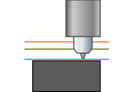
Top Height
- Clearance height: incremental offset from the Clearance Height.
- Retract height: incremental offset from the Retract Height.
- Model top: incremental offset from the Model Top.
- Model bottom: incremental offset from the Model Bottom.
- Stock top: incremental offset from the Stock Top.
- Stock bottom: incremental offset from the Stock Bottom.
- Selected contour(s): incremental offset from a Contour selected on the model.
- Selection: incremental offset from a Point (vertex), Edge or Face selected on the model.
- Origin (absolute): absolute offset from the Origin that is defined in either the Setup or in Tool Orientation within the specific operation.
Top offset
Top Offset is applied and is relative to the Top height selection in the above drop-down list.
 Passes tab settings
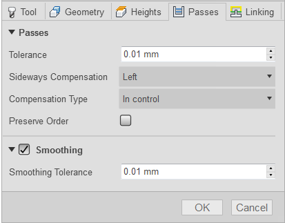
Tolerance
The machining tolerance is the sum of the tolerances used for toolpath generation and geometry triangulation. Any additional filtering tolerances must be added to this tolerance to get the total tolerance.
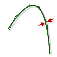
Loose Tolerance .100
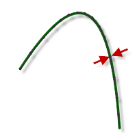
Tight Tolerance .001
CNC machine contouring motion is controlled using line G1 and arc G2 G3 commands. To accommodate this, Fusion approximates spline and surface toolpaths by linearizing them creating many short line segments to approximate the desired shape. How accurately the toolpath matches the desired shape depends largely on the number of lines used. More lines result in a toolpath that more closely approximates the nominal shape of the spline or surface.
Data Starving
It is tempting to always use very tight tolerances, but there are trade-offs including longer toolpath calculation times, large G-code files, and very short line moves. The first two are not much of a problem because Fusion calculates very quickly and most modern controls have at least 1MB of RAM. However, short line moves, coupled with high feedrates, may result in a phenomenon known as data starving.
Data starving occurs when the control becomes so overwhelmed with data that it cannot keep up. CNC controls can only process a finite number of lines of code (blocks) per second. That can be as few as 40 blocks/second on older machines and 1,000 blocks/second or more on a newer machine like the Haas Automation control. Short line moves and high feedrates can force the processing rate beyond what the control can handle. When that happens, the machine must pause after each move and wait for the next servo command from the control.
Sideways Compensation
Determines how to offset the cut from the selected edge. Left and Right are always viewed from the direction of the cut.
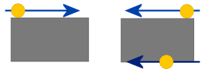
- Left - Compensate Left of the selected edge.
- Right - Compensate Right of the selected edge.
- Center - Puts the cutting head directly on the selected edge.
Left will compensate the head away from the edge, based on these rules.
- For an Outside cut, with a Clockwise chain selection.
- For an Inside cut, with a Counter-Clockwise chain selection.
Changing the direction of the cut requires a Right Compensation direction.
Compensation Type
Specifies the compensation type. Determines where the Kerf width/head position is calculated.
- In computer - The head position is calculated by the program, based on the Kerf diameter and the Sideways Compensation direction. The post-processed output contains the actual compensated position to cut the part to size. The Computer compensates for the width of the Kerf.
- In control - The head position is output as the actual coordinates of the selected chain. Compensation is ''not'' calculated, but instead, compensation codes are output to allow the operator to set the offset amount at the machine tool control. '''The Machine Control compensates for the width of the Kerf.
Outer Corner Mode
When machining outer corners, it may be necessary to avoid rolling around the corner in order to leave the corner perfectly sharp.
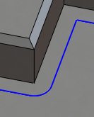
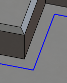
The Outer Corner Mode setting lets you machine outer corners in three different ways.
Outer Corner Mode only appears as an option when Compensation Type is set to In computer.
 |
 |
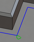 |
| Roll around corner | Keep sharp corner | Keep sharp corner with loop |
| Keeps contact with the corner throughout the motion | Continues the toolpath to a single point corner, losing contact with the material temporarily | Similar to Keep sharp corner, but also performs a horizontal lead-out and lead-in at the corner |
Preserve Order
When Selected, the chains/features are machined in the order in which they were selected. When unselected, the program optimizes the cut order.
As a default Waterjet toolpaths will always be optimized to machine inside boundaries first (slugs), then machine outside boundaries. This keeps the parts from breaking free and moving during a second or third cut on the same part.
Smoothing
Smooths the toolpath by removing excessive points and fitting arcs where possible within the given filtering tolerance.

Smoothing Off

Smoothing On
Smoothing is used to reduce code size without sacrificing accuracy. Smoothing works by replacing collinear lines with one line and tangent arcs to replace multiple lines in curved areas.
The effects of smoothing can be dramatic. G-code file size may be reduced by as much as 50% or more. The machine will run faster and more smoothly and surface finish improves. The amount of code reduction depends on how well the toolpath lends itself to smoothing. Toolpaths that lay primarily in a major plane (XY, XZ, YZ), like parallel paths, filter well. Those that do not, such as 3D Scallop, are reduced less.
Smoothing Tolerance
Specifies the smoothing filter tolerance.
Smoothing works best when the Tolerance (the accuracy with which the original linearized path is generated) is equal to or greater than the Smoothing (line arc fitting) tolerance.
Feed Optimization
Specifies that the feed should be reduced at corners.
Maximum Directional Change
Specifies the maximum angular change allowed before the feedrate is reduced.
Reduced Feed Radius
Specifies the minimum radius allowed before the feed is reduced.
Reduced Feed Distance
Specifies the distance to reduce the feed before a corner.
Reduced Feedrate
Specifies the reduced feedrate to be used at corners.
Only Inner Corners
Enable to only reduce the feedrate on inner corners.
 Linking tab settings
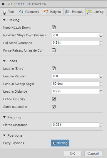
Linking - Keep Nozzle Down
These options can be used to avoid retracts and to avoid previously cut areas.
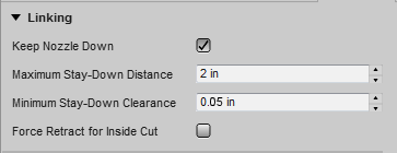
Maximum Stay-Down Distance
The traverse distance where retracts are no longer required.
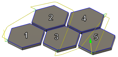
The distance between cuts is Less than 4.0" - The Head stays down at the Top Height - .
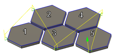
The distance between cuts is Greater than 4.0" - The Head retracts to the Clearance Height.
A smaller distance will cause the head to retract to the Clearance plane. A larger value allows you to stay down at the Top Height.
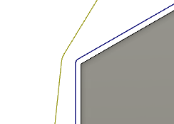
Cut Stock Clearance
Cut part edge clearance, for rapid moves.
 |
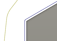 |
| Rapid edge clearance distance of .040" | Rapid edge clearance distance of .200" |
When the Head stays down at the Top Height, this clearance avoids profiles that have been cut. It's an XY clearance to the closest edge, when making a rapid move between cuts and the Head is down.
Force Retract for Inside Cut
Use this checkbox to force a retract, for all moves that are contained inside of a part model.
Leads - Lead-In (Entry)
Enables a contour blend onto the profile.
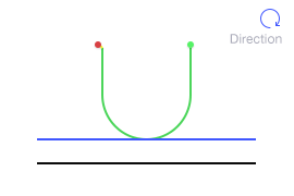
The Lead In/Out move allows you to blend onto the part profile. Without this type of blend you could leave a mark at the starting point.
Lead-In Radius
Specifies the radius for lead-in moves.
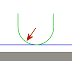
The radius blend allows for a smooth transition into the cut.
Lead-In Sweep Angle
Specifies the sweep angle of the Lead-in arc.
 |
 |
| Sweep Angle of 90 degrees | Sweep Angle of 45 degrees |
Linear Lead-In Distance
Specifies the length of the linear lead-in move. Required if using machine cutter compensation.
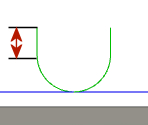
Linear Lead-In Length
Lead-Out (Exit)
Enables a contour blend off of the profile.

The Lead In/Out move allows you to blend off of the part profile. Without this type of blend you could leave a mark at the starting point.
Same as Lead-In
When checked, specifies that the lead-out values should be identical to the lead-in values.
 |
 |
| Lead-Out identical to Lead-In | Lead-Out different than Lead-In |
Linear Lead-Out Distance
Specifies the length of the linear Lead-Out move.
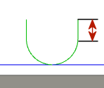
Required if using machine cutter compensation.
Lead-Out Radius
Specifies the radius for lead-out moves.
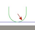
The radius blend allows for a smooth transition off of the cut.
Lead-Out Sweep Angle
Specifies the sweep angle of the Lead-Out arc.
 |
 |
| Sweep Angle of 90 degrees | Sweep Angle of 45 degrees |
Piercing
Piercing Clearance lets you specify a distance away from the part profile to safely pierce the material, before starting the contour. This value is in addition to the Lead In distance values.
Entry positions
Select geometry near the location where you want the tool to enter.