Generate a 2D Profile toolpath
On the Manufacture workspace toolbar, click Fabrication > Cutting > 2D Profile
 .
.The 2D Profile dialog opens.
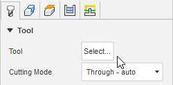
On the Tool tab, click Select to pick a tool. If you have not created a tool to use, in the left panel of the dialog, from the Fusion Library, pick a tool from the Sample Tools library.
Tip: Select a laser cutter, waterjet, or plasma cutter.
On the Geometry tab, with Contour Selection active, select faces, edges, or sketches that represent where you want to cut.

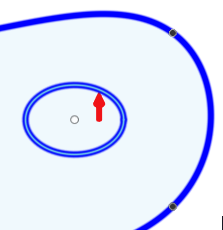
If you select an edge or sketch, verify that the contour arrows are pointing in the correct direction. For internal geometry, contour arrows should point counterclockwise and for outside should point clockwise. If necessary, click the contour arrow to flip its direction.
Optional steps:
- To keep the part secured to the sheet of material until the machining process is complete, in the Geometry tab, select the Tabs checkbox.
- To avoid retracts and moving over previously cut areas, in the Linking tab, select the Keep Nozzle Down checkbox.
- To ensure material around the tool entry position is completely clear, specify a Finishing Overlap distance.
Click OK.
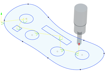
The toolpath is generated.
