Activity 1: Open the sample file and create a setup
In this activity you open the sample, 2D Adaptive Milling Tutorial, from the Tutorials folder in the CAM samples section of the Data panel, save it to a personal folder, switch to the Manufacture workspace, and check that the units are set to inches. Then you create a Setup, set the stock point in the top left corner of the part, and use the following settings to add stock to the sides, top, and bottom of the Stock Box:
- Set the Stock Side Offset to 0 in
- Set the Stock Top Offset to 0 in
- Set the Stock Bottom Offset to 0.2 in
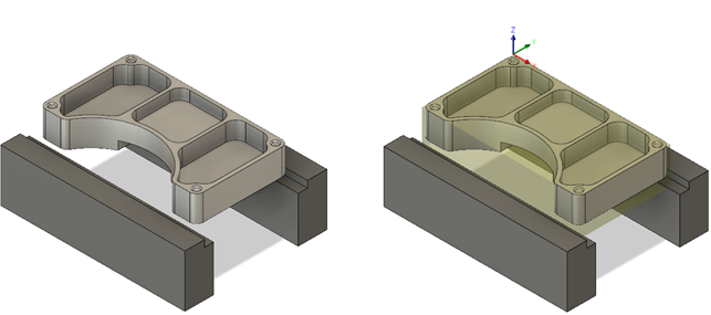
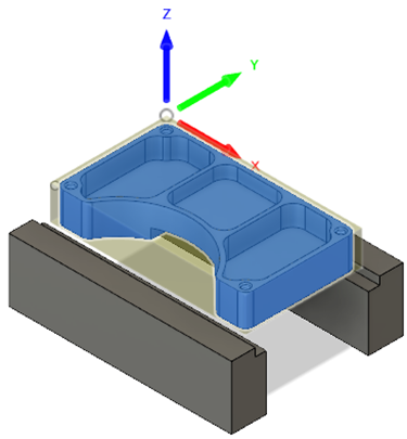
Sample file opened (left). New Setup created (right).
Steps
Open the part 2D Adaptive Milling Tutorial part.
If necessary, click Show Data Panel.
In the Data Panel, in CAM Samples, double-click Tutorials > 2D Adaptive Milling Tutorial.
Note: When you open a sample model in Fusion for the first time, it appears in the Design workspace.
Save a copy of the model to a personal folder.
On the Application Bar, click File > Save As.
Choose a project and folder, or create new ones.
Click Save.
In the Change Workspace toolbar select Manufacture, to switch to the Manufacture workspace.
Switch units from mm to inches.
In the Browser, to the right of the Units, click Change Active Units.
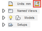
Select Inches from the drop-down menu.
Click OK.
Specify the work coordinate system (WCS) by specifying the orientation and setting the stock point at the top left-hand corner of the part. Then select the part within the stock bounding.
On the Manufacture toolbar, Milling tab, select Setup > New Setup
 .
.The Setup tab
 is selected by default.
In the Work Coordinate System (WCS) group, from the Orientation drop-down menu, select Select Z axis/plane & X axis.
Make sure the Z Axis button is active and select the vertical edge on the clamp as shown in the following image.
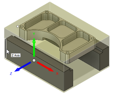
From the Origin drop-down list, make sure that Stock box point is selected.
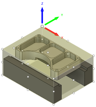
Click the Box Point button
 and select the point (represented by a white dot) at the top left-hand corner of the part as shown in the following image.
 Note: The Model button shows that currently nothing
 is selected.
Click the Model button and select the part within the stock bounding.
After selection, the part is highlighted within the stock bounding box, and the Model button says
 .Note: Don’t click OK, yet. Instead, proceed to the next step.
Specify the size of the stock. Use the Relative size box, select Add stock to sides and top-bottom in the Stock Offset Mode, and add a 0.2 inch offset to the stock bottom while adding no offset on any other side.
Click the Stock tab
 .
.From the Mode drop-down menu, select Relative size box.
From the Stock Offset Model drop-down menu, select Add stock to sides and top-bottom.
Set the Stock Side Offset to 0 in.
Set the Stock Top Offset to 0 in.
Set the Stock Bottom Offset to 0.2 in.
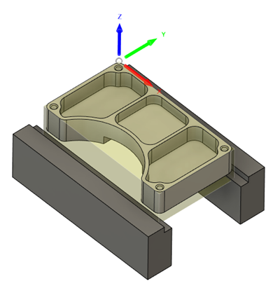
Click OK to create the Setup and close the dialog.
Activity 1 summary
In this activity you opened the sample, 2D Adaptive Milling Tutorial, saved it to a personal folder, switched to the Manufacture workspace, and checked that the units were set to inches. Then you created a new Setup, set the stock point in the top left corner of the part, and used the following settings to size the stock:
- Stock Side Offset: 0 in
- Stock Top Offset: 0 in
- Stock Bottom Offset: 0.2 in

Sample file opened (left). New Setup created (right).