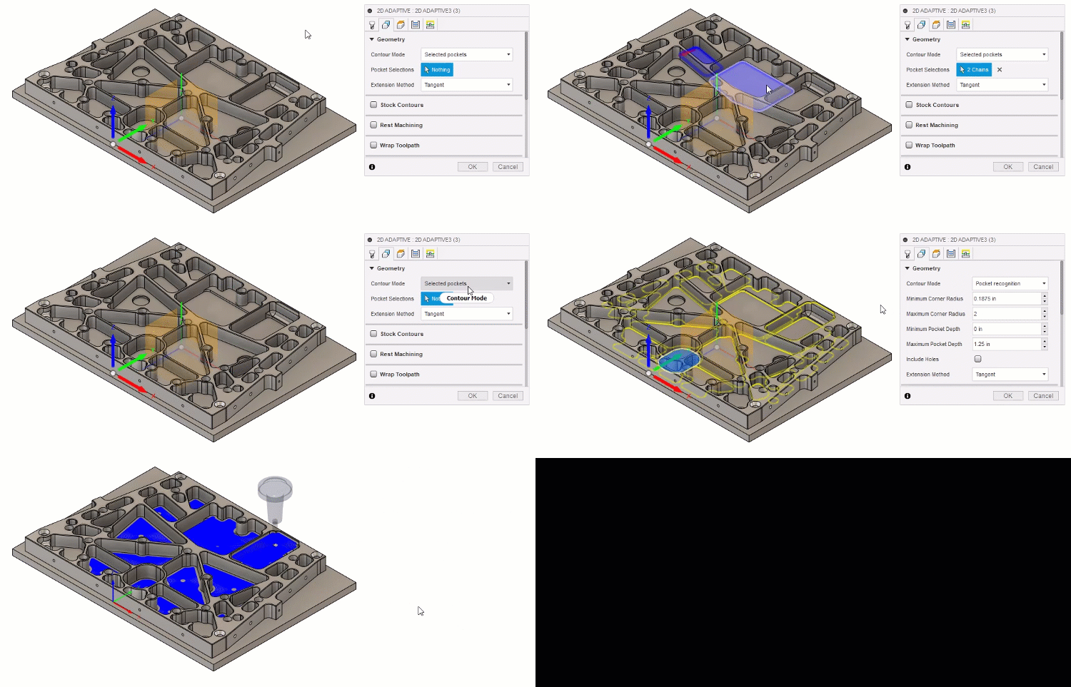
2D pocket recognition
Pocket recognition automates the process of selecting closed pockets when programming toolpaths. This can provide significant time savings when programming parts that have numerous pockets of different sizes. Pocket recognition only selects edges, and not faces. Pocket recognition is available only for 2D Contour, 2D Adaptive, and 2D Pocket.
When creating a toolpath, you control the pocket selection by specifying ranges of a pocket's corner radius and depth.
The animation below shows the difference between manually selecting pockets and using pocket recognition to automatically select the pockets.

Corner radius
The corner radius refers to the internal radius of the corners of the model. The Minimum Corner Radius value should match, or be greater than, the radius of the tool that you are machining with.

When in the Manufacture workspace, you can use the Inspect > Measure tool to check the radius of internal corners on pockets. You can also click a corner-edge on the canvas and view the radius information in the bottom-right of the canvas.
For a pocket to be selected by pocket recognition, all its corner radii need to be within the specified Minimum Corner Radius and the Maximum Corner Radius values.
In the example below, the smallest corner radius is 2 mm and the largest corner radius is 7 mm. For the pocket to be recognized, the Minimum Corner Radius needs to be equal to, or smaller than 2 mm, and the Maximum Corner Radius needs to be equal to, or larger than 7 mm.

Minimum Corner Radius = 2 mm

Maximum Corner Radius = 7 mm
Pocket depth
The pocket depth is relative to each pocket, which is measured as the distance between the top and the bottom of the pocket.

You can use the Minimum Depth and Maximum Depth parameters to control which pockets are recognized. In the example below, the depth of the pockets, starting from the left, are 5 mm, 10 mm, and 15 mm. To recognize only the 10 mm, middle pockets, you have to enter a Minimum Depth larger than 5 mm and a Maximum Depth smaller than 15 mm.

Holes and circular pockets
Geometrically, holes and circular pockets are the same. Use the Include Holes parameter to allow pocket recognition to consider circular pockets and holes in the selection, then use the Minimum Hole Diameter to control which circular pockets and holes are selected. The Minimum Corner Radius also restricts which circular pockets are selected. Quite often, the Minimum Corner Radius is set to equal the radius of the tool that you are using, meaning any circular pockets that the tool does not fit in are not included in the selection.
In the example below, when Include Holes is selected. Pocket recognition selects all the circular pockets and holes that are present in the model.

If you want to only machine the two circular pockets and not include the four holes that are in the corners, enter a Minimum Hole Diameter that is larger than the diameter of the holes in the corners.

This video explains how and when to use the Pocket Recognition selection option.
Length: 3:50