Add a Volume Support structure
This feature is part of an extension. Extensions are a flexible way to access additional capabilities in Fusion. Learn more.
Ensure that you have an additive setup with an MPBF, eBeam, SLA/DLP, or binder jetting additive machine selected.
On the Manufacture workspace toolbar, click Additive > Supports > Volume Support
 .
.The Volume Support dialog opens.
With Selection active, on the canvas, click the solid bodies, the faces of solid bodies, or the mesh face groups that you want supported.
Tip: To prevent supports generating at certain areas, select the Avoid checkbox, ensure Avoided Model is active, and then, on the canvas, click the solid bodies, the faces of solid bodies, or the mesh face groups.Enter a Support Overhang Angle between 0 degrees and 90 degrees to specify the angle from the horizontal plane at which supports are needed.
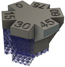
Example of volume supports that are generated on a part when using a Critical Support Angle of 35 degrees.
In the General tab, in the Structure group, choose a Structure Type option.
- Solid: Uses a square column-style of support.
- Surface: Uses a cross-hatching-style of support.
Optional steps:
To enforce a distance between these supports and any other existing supports so that they do not overlap, in the Geometry tab, select the Distance to Other Support checkbox, and then enter a Distance.
To enable rotation of the detected support area, in the Geometry tab, select the Rotate Support Area checkbox.
If you chose a Structure Type of Surface, in the Volume Properties tab, select the Hole checkbox then choose a Hole Pattern and Structure Density to determine the type of support structure to use.
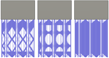
Example of Diamond (left), and Oval (middle) hole patterns, and a structure with the Holes checkbox deselected (right).
To splinter the supports so that they are easier to break off after the build process is complete, in the Raster and Contour tab, select the Fragment Size and Gap checkbox, and then choose options for Fragment Size and Fragment Gap.
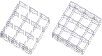
Example of supports fragmented (left) and not fragmented (right).
If you chose a Structure Type type of Surface, in the Connections tab, choose options for how the supports connect to the top or bottom of the part and to the build platform.

Example of Breaking Point connections.
To ensure supports from the selected faces, bodies, or components are in direct contact with the build platform, in the Angled Volume Support tab, select the Angled Support checkbox, then adjust the manipulator on the canvas to change the direction and tilt of the angled supports.
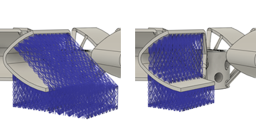
Example of Angled Supports selected (left) and deselected (right).
Note: Angled volume supports are angled with respect to the component's local coordinate system. Re-positioning a component causes any angled volume supports to become out of date. Rotating a component about the X and Y axes can prevent the angled volume supports from being regenerated.
Click OK.
The supports are generated and, in the Browser, under the Supports node, a Volume Support child item is added.
Tip: To reuse these support settings in the future, right-click the child item and choose Store as Template to add it to the Template Library.
If the setup uses an MPBF or eBeam additive machine, you can now generate, and then simulate, the additive toolpath. Otherwise, export the build file.