Move or rotate a component in a build volume
Ensure that you have an additive setup with an additive machine selected.
On the Manufacture workspace toolbar, click Additive > Position > Move Components
 .
.The Move Components dialog opens.
Tip: You can preselect components before starting the command; the selection is retained when the dialog opens. Preselecting also allows you to use rectangle select and other selection tools that are not available while the command is active.By default, if the active setup contains only one component, that component is automatically selected. If the setup contains multiple components, on the canvas, select the components you want to work with.
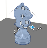
The manipulator shows on top of the component and the dialog updates to show additional parameters.
Select a Move Type. Choose:
 Free Move to move along, and rotate about, the X, Y, and Z axes.
 Translate to move along the X, Y, and Z axes.
 Rotate to rotate about the X, Y, and Z axes
 Point to Point to move from one selected point to another.
 Point to Position to move from one selected point to a specified XYZ location.
If you selected a Move Type of Free Move, Translate, or Rotate:
Choose the Coordinate System to specify the direction in which the selected components are moved or rotated.
Move or rotate in relation to the component's coordinate system or in relation to the additive machine's coordinate system.
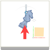
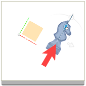
Machine XYZ (left) and Component XYZ (right).
(Optional) If you selected Free Move or Rotate and multiple components, select the Rotate Individually checkbox to rotate each selected component about its respective local axes instead of rotating all components together around a shared pivot. Deselect to rotate all selected components together.
Note: Set Pivot is unavailable when Rotate Individually is selected.(Optional) To change the location of the handles on the canvas, click Set Pivot
 , then, on the canvas, click a point, then click Done.
On the canvas, click and drag the distance handles, or rotation handles, on the manipulator to move the components along, or rotate the components about, the X, Y, and Z axes.
The parameters in the dialog update as you move or rotate the handles.
If you selected a Move Type of Point to Point:
With Origin Point active, on the canvas, select a point on a component to move from.
With Target Point active, on the canvas, select a point on a component to move to.
If you selected a Move Type of Point to Position:
With Point active, on the canvas, select a point on a component.
Choose the Coordinate System to specify the direction in which the selected components are moved.
Enter a Position X, Position Y, and Position Z to specify the point's new location.
(Optional) To highlight in red all components that would overlap after the operations is completed, select the Display Interference checkbox.
(Optional) To move the selected components in the XY plane to a fixed location on the build volume, click one of the following:
Move to platform front-left
 to move the center of the selected components to the front-left corner of the build volume. For machines with rounded corners, the center is placed as close as possible to that location.
Move to platform center
 to move the center of the selected components to the center of the build volume.Note: Both options move components in the XY plane only. The Z position of the components does not change.
Click OK.