Feature Construction reference
This feature is part of an extension. Extensions are a flexible way to access additional capabilities in Fusion. Learn more.
Use the Feature Construction dialog to specify the details of a Feature Construction additive toolpath.
Manufacture > Additive > Multi-Axis > Feature Construction ![]()
The dialog contains the following settings:
Tool
Specifies the depositing tool. Choose an electric arc wire, laser powder, or laser wire tool.
Bead Width
Specifies the width of the melted material used to deposit the features.
Example of a small bead width (left) and a large bead width (right) during stock simulation:
The bead is different to the material feedstock (such as wire or powder) that is supplied to the machine.
Depositing Feedrate
Specifies the travel speed of the deposition head when depositing the bead of material.
Example of bead being deposited during stock simulation:
Lead-In Feedrate
Specifies the travel speed of the deposition head when leading into a depositing move.
Lead-Out Feedrate
Specifies the travel speed of the deposition head when leading out from a depositing move.
Plunge Feedrate
Specifies the travel speed of the deposition head when moving toward a layer to deposit the melted material.
Base Type
Specifies the form of the base surface on which to deposit the features.
- Plane: A flat surface in the XY plane.
- Cylinder: A cylindrical surface.
- Surface of Revolution: A surface generated by revolving a curve around the X axis.
- Arbitrary: A free-form surface.
Base
Defines the base surface.
On the canvas, click one or more faces.
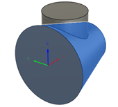
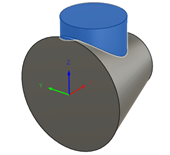
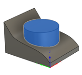
From left to right, example of a flat surface in the XY plane, a cylindrical surface, a surface generated by revolving a curve, and a free-form surface:
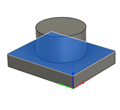
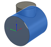
Feature
Defines the features that you want to deposit.
On the canvas, click bodies or the faces of bodies.
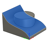
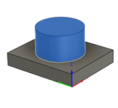
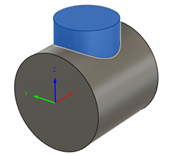
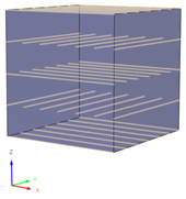
From left to right, example of a feature on a plane base, a cylindrical base, a surface-of-revolution base, and an arbitrary base:
Tool Orientation
Overrides the tool orientation defined in the setup.
For more information, see Tool orientation overview.
Model
Overrides the model geometry (surfaces or bodies) defined in the setup.
Clearance Height
Specifies the first height the tool rapids to on its way to the start of the additive toolpath.
Retract Height: Incremental offset from the Retract Height.
Model Top: Incremental offset from the Model Top.
Model Bottom: Incremental offset from the Model Bottom.
Selection: Incremental offset from a point (vertex), edge, or face selected on the model.
Origin (Absolute): Absolute offset from the origin that is defined in the setup or in the Tool Orientation group.
Retract Height
Specifies the height that the tool moves up to before the next pass.
Clearance Height: Incremental offset from the Clearance Height.
Model Top: Incremental offset from the Model Top.
Model Bottom: Incremental offset from the Model Bottom.
Selection: Incremental offset from a point (vertex), edge, or face selected on the model.
Origin (Absolute): Absolute offset from the origin that is defined in the setup or in the Tool Orientation group.
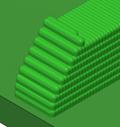
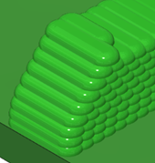
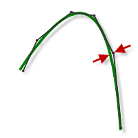
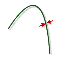
Tolerance
The machining tolerance is the sum of the tolerances used for toolpath generation and geometry triangulation. Any additional filtering tolerances must be added to this tolerance to get the total tolerance.
Example of a loose tolerance (left) and a tight tolerance (right):
 |
| 
CNC machine contouring motion is controlled using line G1 and arc G2 G3 commands. To accommodate this, Fusion approximates spline and surface toolpaths by linearizing them; creating many short line segments to approximate the desired shape. How accurately the toolpath matches the desired shape depends largely on the number of lines used. More lines result in a toolpath that more closely approximates the nominal shape of the spline or surface.
Data Starving
It is tempting to always use very tight tolerances, but there are trade-offs including longer toolpath calculation times, large G-code files, and very short line moves. The first two are not much of a problem because Fusion calculates very quickly and most modern controls have at least 1 MB of RAM. However, short line moves, coupled with high feedrates, may result in a phenomenon known as data starving.
Data starving occurs when the control becomes so overwhelmed with data that it cannot keep up. CNC controls can only process a finite number of lines of code (blocks) per second. That can be as few as 40 blocks/second on older machines and 1,000 blocks/second or more on a newer machine like the Haas Automation control. Short line moves and high feedrates can force the processing rate beyond what the control can handle. When that happens, the machine must pause after each move and wait for the next servo command from the control.
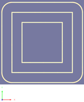
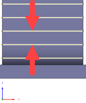
Stepover
Specifies the horizontal stepover between infill passes on a layer.
Infill
Adds infill passes inside the feature.
The additive toolpath slices the features in layers. Each layer is made up of perimeter passes, infill passes, or both.
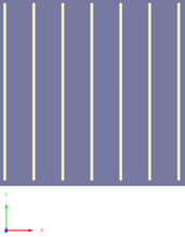
From left to right, example of infills only, perimeters only, and infills and perimeters:


Stepover Allowance
Specifies the percentage deviation from the horizontal stepover.
The stepover gets adjusted to allow a more even deposition across the base surface. For example, if the stepover is 10 mm and the stepover allowance is 10%, the stepover can vary between 9 mm and 11 mm.
Example of 0% (left) and 10% (right):
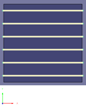
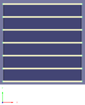
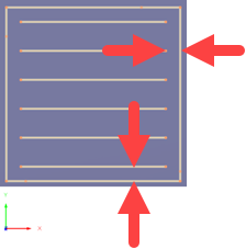
Direction
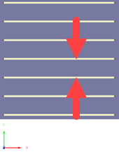
Controls whether depositing during infill passes happens in one direction only (One Way) or in both directions (Two Way).
Example of infills when One Way is chosen (left) and when Two Way is chosen (right):
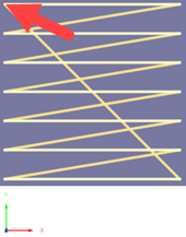
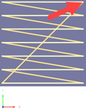
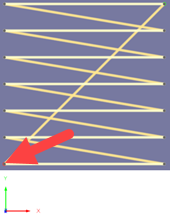
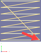
Start Corner
Specifies the start position of infill passes in relation to the WCS.
From left to right, example of Upper Left, Upper Right, Lower Left, and Lower Right:
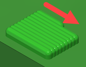
Start Position
Controls the direction of travel for infill passes along the X axis.
Example of infill passes traveling along a cylinder-type base from a start position of Minimum X (left) and from a start position of Maximum X (right):
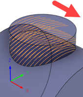
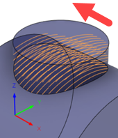
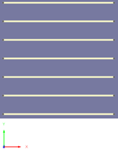
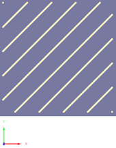
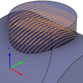
Angle
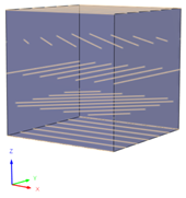
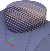
Specifies the angle of infill passes on the first layer, measured counterclockwise from the X axis around the Z axis.
From left to right, example of 0 degrees, 45 degrees, and 90 degrees:
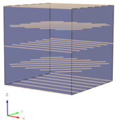
Angular Pattern
Controls how infill passes are repeated as the layers progress upwards.
Example of Rotation Angle of 45 degrees (left) and Alternate Angle of 45 degrees (right):
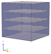
Rotation Angle
Specifies the increase in angle for each successive layer of infill passes. The angle is measured counterclockwise from the X axis around the Z axis.
Example of 25 degrees (left) and 45 degrees (right):
Alternate Angle
Specifies the angle for every other layer of infill passes. The angle is measured counterclockwise from the X axis around the Z axis.
Example of 45 degrees (left) and 90 degrees (right):
Rotary Direction
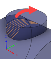
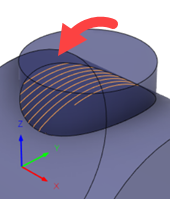
Controls the direction of travel for infill passes, as perceived by looking down the X axis.
Example of infill passes traveling across a cylinder-type base in a clockwise (left) and a counterclockwise (right) direction:
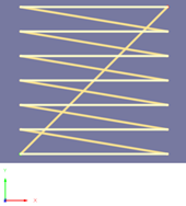
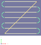
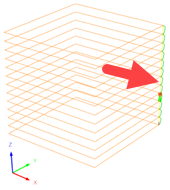
Style
Controls whether infill passes are along or across the X axis.
Example of Along chosen (left) and Across chosen (right):
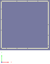
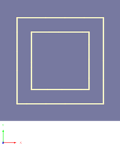
Perimeter
Adds perimeter passes around the feature.
The additive toolpath slices the feature in layers. Each layer is made up of perimeter passes, infill passes, or both.
From left to right, example of infills only, perimeters only, and infills and perimeters:
Order
Controls whether the perimeter passes are added before or after the infill passes.
Gap Width
Specifies the space between the perimeter passes and the infill passes.
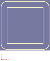
Extent
Controls how any added thickness is applied to the edge of the feature.
Number of Passes: Lets you specify a number of extra passes offset outwards and inwards of the perimeter passes.
Distance: Lets you specify a distance outward and inward of the perimeter passes and automatically add as many extra passes as possible based on the stepover.
From left to right, example of Offset Outwards chosen, Offset Inwards chosen, and Offset Outwards and Inwards chosen:
Outward Offsets
Specifies the number of extra passes offset outwards from the perimeter passes. A positive, non-zero value adds thickness outside the wall of the feature.
Inward Offsets
Specifies the number of extra passes offset inwards from the perimeter passes. A positive, non-zero value adds thickness inside the wall of the feature.
Minimum Outward Distance
Specifies the distance offset outwards from the perimeter passes. Within this offset, extra passes are automatically added based on the stepover.
Minimum Inward Distance
Specifies the distance offset inwards from the perimeter passes. Within this offset, extra passes are automatically added based on the stepover.
Rotation Within Layers
Specifies the increase in angle of the start position for perimeter passes on the same layer. The angle is measured counterclockwise from the X axis around the Z axis.
Varying the start positions prevents a visible seam from forming on the deposited bead.
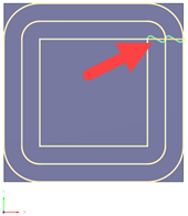
Example of 0 degrees causing a seam.
Rotation Between Layers
Specifies the increase in angle of the start position for perimeter passes on successive layers. The angle is measured counterclockwise from the X axis around the Z axis.
Varying the start positions prevents a visible seam from forming on the deposited bead.
Example of 0 degrees causing a seam.
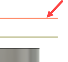
Offset from Base
Specifies the distance between the base surface and the first layer of passes.
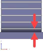
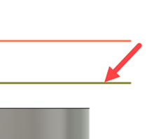
Layer Thickness
Specifies the distance between each successive layer of passes.
Tool Axis
Adds extra tool-axis controls, such as how far the tool can tilt forwards, or backwards, and sideways.
Tool-axis controls help to keep the head of the deposition tool at a certain angle during deposition
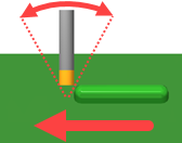
Forward Tilt
Specifies the number of degrees that the tool should tilt forwards (positive) or backwards (negative) with reference to the direction of travel.
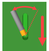
Sideways Tilt
Specifies the number of degrees that the tool should tilt sideways with reference to the direction of travel.
Mode
Controls the tool axis for perimeter passes.
Base Surface Normal: Keeps the tool axis normal to the base surface.
Towards Previous Layer: Aligns the tool axis tangent to the surface slope.
Retraction Policy
Controls how the tool moves between passes.
Full Retraction: Completely retracts the tool to the Retract Height at the end of the pass before moving above the start of the next pass.
Minimum Retraction: Moves straight up to the lowest height where the tool clears the workpiece, plus any specified safe distance.
Shortest Path: Moves the tool the shortest possible distance in a straight line between paths.
Important: The Shortest Path option should not be used on machines that do not support linearized rapid movements where G0 moves are straight-line (versus G0 moves that drive all axes at maximum speed, sometimes referred to as "dogleg" moves). Failure to obey this rule will result in machine motion that cannot be properly simulated by the software and may result in tool crashes.
For machines that do not support linearized rapid moves, the post processor can be modified to convert all G0 moves to high-feed G1 moves. Contact technical support for more information or instructions how to modify post processors as described.
Safe Distance
Specifies the minimum distance between the tool and the part surfaces during retract moves. The distance is measured after stock to leave has been applied, so if a negative stock to leave is used, special care should be taken to ensure that safe distance is large enough to prevent any collisions.
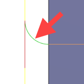
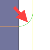
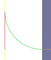
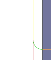
Lead-In
Specifies the radius for lead-in moves.
Example of a 2 mm radius (left) and a 0.5 mm radius (right):
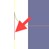
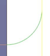
Lead-Out
Specifies the radius for lead-out moves.
Example of a 0.5 mm radius (left) and a 2 mm radius (right):

Transition Type
Specifies the type of connection done between passes.
- No contact: Sidesteps are not connected with each other on the same Z-level, but connected with a retract move.
- Straight line: Simpler, direct connections using straight lines.
- Shortest path: The shortest possible path between machining areas - typically a move in a straight line.
- Smooth: Use smooth tangential movements using true arcs where appropriate.