Generate an Inspect Surface operation for a live part alignment
This feature is part of an extension. Extensions are a flexible way to access additional capabilities in Fusion. Learn more.
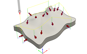
After you have specified the type of transformation that Fusion uses to calculate the part alignment, generate an Inspect Surface operation to specify which points to probe on the part's surface. The surface inspection results are used to calculate the part alignment and update the work coordinate system (WCS) on the machine controller for the remaining operations in the setup.
In the Live Part Alignment contextual environment, click Inspect Surface
 .
.The Inspect dialog opens.
On the Tool tab, click Select to pick a probe. If you have not created a probe to use, in the left panel of the dialog, from the Fusion Library, pick a probe from the Probes folder.

On the Geometry tab, make sure that Positions is active, then, on the canvas, click the model to specify points to be inspected by the probe.
Tip: Try to ensure a spread of points over the part to lock the translation and rotation axes.Enter values for the Upper Tolerance and Lower Tolerance to specify a tolerance band.
Optional steps:
To compensate for surface thickness, enter a positive or negative Surface Offset value.
Tip: Applying a surface offset is useful when the model is not representative of the part that is being probed. For example, when the model is of the final machined part and not the starting shape.To change the distance at which the probe starts to approach a point at the Measure Feedrate, change the Approach value.
To stop the CNC machine, and display a message on the controller, when a point is out of tolerance, in the Actions tab, select the Out of Position checkbox.
Tip: Edit the Extra Tolerance for Lower Alarm and Extra Tolerance for Upper Alarm settings in the Compare and Edit dialog to adjust the alarm trigger thresholds for out-of-tolreance points. To open the dialog, in the Browser, right-click the Inspect Surface operation and choose Compare and Edit.
Click OK.
The operation is generated.

Now post process all the operations to create NC code, which you can then transfer to the machine controller. When you run the NC code, import the inspection results in real-time using the live connection between Fusion and the CNC machine.