Select surfaces to avoid/machine
The actions you can specify for the tool to perform on a surface group are: Avoid, Machine, Ignore, and Fixture. The following examples show some scenarios where it can be useful to use the Avoid/Machine Surfaces when programming toolpaths.
Select surfaces to avoid
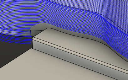
In the example below, the flat toolpath is machines the floor and the wall in the outermost pass. While this may be desirable in certain scenarios, in this case you may want to avoid machining the floor and the wall at the same time to avoid excessive load on the tool. To avoid machining the wall, you can select the wall surface and set the action to Avoid.
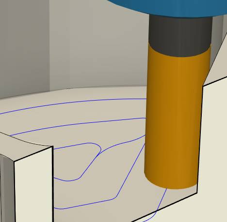
Flat toolpath machining floor and wall.
In the operation dialog, go to the Geometry tab.
In the Avoid/Machine Surfaces group, click
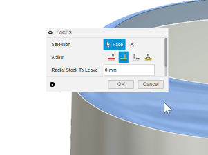
 to add a surface group. The Faces dialog opens.
With the Selection button active, select the wall surfaces on the model that you want to avoid.
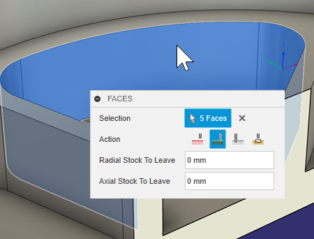
Selecting wall surfaces to avoid.From the Action group of buttons, select Avoid.
Specify a Radial Clearance and an Axial Clearance.
Click OK.
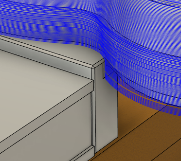
After generating the toolpath, you can see that the flat toolpath now machines the floor but avoids the wall by the radial clearance value.
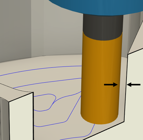
Tool avoids wall because of radial clearance.
Select surfaces to machine
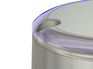
In the example below, a steep and shallow toolpath is machining a fillet using a machining boundary. As the machining boundary is a projection of the geometry in 2D, it may be better to use the Avoid/Machine Surfaces group to machine the fillet.
In the operation dialog, go to the Geometry tab.
In the Avoid/Machine Surfaces group, click
to add a surface group. The Faces dialog opens.With the Selection button active, select the fillet surfaces on the model that you want to machine.
Selecting fillet surface to machine.(Optional) If the surface has closed pockets or holes you want to machine through, select Machine Over Holes/Pockets.
From the Action group of buttons, select Machine.
Note: For some operations, the entire model is automatically set to Machine. To cut only specific surfaces, you may need to set the model to Avoid.Click OK.
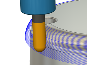
After generating the toolpath, the steep and shallow toolpath now machines the fillet with better toolpath confinement.
Select surfaces to ignore
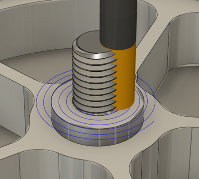
In the example below, the part is held by screws for certain operations. When the operations are complete and the screws no longer are needed, they can be removed from the physical part. Instead of editing the design to remove the screws, you can specify the screws as surfaces or bodies to Ignore. This tells the tool to treat them as if they don't exist, allowing it to safely pass through them during toolpath generation.
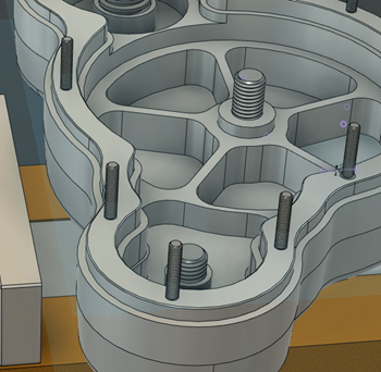
Screws to hold a part.
In the operation dialog, go to the Geometry tab.
In the Avoid/Machine Surfaces group, click
to add a surface group. The Faces dialog opens.With the Selection button active, from the Browser, select the bodies that the tool should ignore.
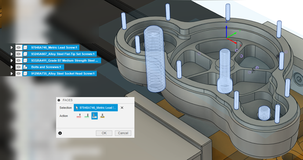
Selecting bodies to ignore.From the Action group of buttons, select Ignore.
Click OK.
Once the toolpath is generated, the tool will cut the face and treat the screws as ignored surfaces, allowing it to pass through them.
Tool ignores screws.
Select fixture surfaces to avoid
In the example below, a part is held by a fixture but the toolpath is on the part and the fixture. To avoid machining the fixture, you can select the fixture surfaces and set the action to Fixture, which avoids the fixture by the specified clearances.
You can specify fixture surfaces in the Setup dialog or in the Avoid/machine surfaces group. If you specify fixture surfaces in the Setup dialog, the fixture surfaces are automatically added to the Avoid/Machine Surfaces group in the Geometry tab. If you did not specify fixture surfaces in the Setup dialog, you can add them in the Geometry tab.
In the Setup dialog, with the Fixture button active, select the bodies that make up the fixture.
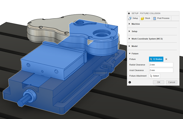
Selecting fixture bodies.Specify a fixture Radial Clearance and an Axial Clearance then click OK.
Create a toolpath and then go to the Geometry tab.
In the Avoid/Machine Surfaces group, because you specified the fixture in the Setup dialog, a fixture surface group appears automatically.
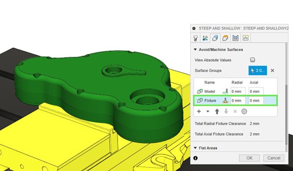
If you did not specify any fixture surfaces in the setup, click
to add a fixture surface group. The Faces dialog opens to let you select fixture surfaces.Specify any additional Radial and Axial fixture clearances.
Click OK.
After generating the toolpath, you can see that the flat toolpath now machines the part and avoids the fixture by the specified clearances.
Create a selection set from a surface group
This feature is part of an extension. Extensions are a flexible way to access additional capabilities in Fusion. Learn more.
In the toolpath dialog, in the Geometry tab, in Avoid/Machine Surfaces table, right-click a surface group row.
Select Create Selection Set from context menu.
A new selection set is created in the Browser, in the Selection Sets folder with the same name as the surface group.