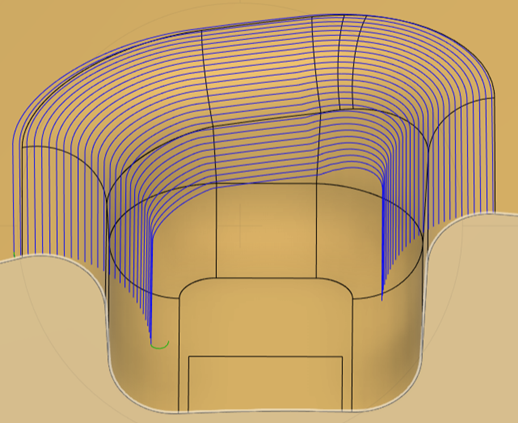
Generate a Blend toolpath
On the Manufacture workspace toolbar, click Milling > 3D > Blend
 .
.The Blend dialog opens.
On the Tool tab, click Select to pick a tool. If you have not created a tool to use, in the left panel of the Tool Library dialog, pick a tool from the Fusion Library.
Note: To machine undercuts, select one of the following tool types: lollipop mill, dovetail mill, or slot tool.On the Geometry tab, next to Drive Surfaces, click Select and select surfaces to machine.
Tip: You can use window selection on the canvas to select multiple faces at once.Select an Offset Passes Using option to guide how the toolpath follows the geometry. Choose:
- Surface Boundary to use the boundary of the selected drive surfaces.
- Curve Selection to offset between two curves, creating evenly spaced stepovers if the curves are parallel.
If you select the Offset Passes Using option of Curve Selection, next to Drive Curves, click Select, then select curves to guide the toolpath creation:
Select a start drive curve on the perimeter of the machined region. This curve must be the first in the list and defines one edge of the machined region.
(Optional) Select one or more intermediate drive curves. Each must be a surface edge within the machined region and lie between the start and end curves. Intermediate curves create smoother toolpath progression when the start and end curves are quite different. The order of intermediate curves in the list does not matter.
Select an end drive curve on the opposite perimeter of the machined region. This curve must be the last in the list.
(Optional) To reorder drive curves, use the arrow controls in the Drive Curves list. Ensure the start drive curve is first and the end drive curve is last.
Note: Which curve you set as start and which as end (on the same section of geometry) affects how the strategy creates the toolpath.Optional steps:
On the Passes tab, on the Stepover Calculation drop-down list, change the default option if needed.
From tip of tool - Useful for machining areas where the tool cannot contact all the points on a surface because of its cutting geometry. It calculates the stepover between one pass and the next relative to the previous position of the tool tip.
On surface - Can detect and machine undercuts. It calculates the stepover relative to curves on the surface of the part.
To machine areas that are unreachable by 3-axis machining, on the Tool tab, from the Machining Type group, select 5-axis.
Note: Access to the Fusion Manufacturing Extension is required to create multi-axis toolpaths.On the Passes tab, to add entry passes before the start drive curve:
Select the Entry Passes checkbox.
Enter the Number of Passes to specify how many additional passes to add before the start drive curve. Each pass is offset from the previous one, creating a gradual approach to the model.
Enter the First Height to set how high the first entry pass is raised from the model surface. The height is measured along the contact normal, which is perpendicular to the surface at the point where the tool contacts it. The height of each subsequent pass decreases gradually, reducing to zero at the start drive curve.
On the Passes tab, to add exit passes after the end drive curve:
Select the Exit Passes checkbox.
By default, the Same as Entry checkbox is selected, which uses the same number of passes and maximum height as the entry passes. If you want to specify different values for the exit passes, deselect Same as Entry.
If you deselected Same as Entry, enter the Number of Passes and the Final Height for the end drive curve.
Click OK.