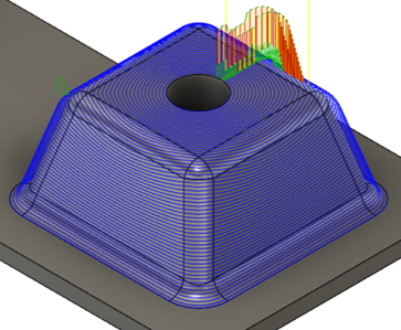
Generate a Geodesic toolpath
On the Manufacture workspace toolbar, click Milling > 3D > Geodesic
 .
.The Geodesic dialog opens.
On the Tool tab, click Select to pick a tool. If you have not created a tool to use, in the left panel of the Tool Library dialog, pick a tool from the Fusion Library.
Note: Select a tool with a spherical tip, such as ball end mills or lollipop mills.On the Geometry tab, next to Drive Surfaces, click Select to select one or more surfaces to machine.
Note: If you select several surfaces, they need to be joined.Optional steps:
To contain the toolpath area with a Machining Boundary, select one or more silhouettes or sketches as boundaries.
By default, the Machining Boundary is evaluated automatically based on the selected Drive Surfaces.
Select a Type of Passes:
Blend - Creates a toolpath by morphing between selected curves. Typically used with curves selected on opposite sides of the machined region. The resulting passes are modified versions of the drive curves, creating a smooth transition across the surface. Intermediate curves guide how this transition is shaped. Stepovers may have a variable distance.
Scallop - Creates a toolpath by offsetting one or more selected curves. Each curve is preserved as much as possible while being offset, and passes merge where offsets intersect. Useful for maintaining a consistent scallop height across complex boundaries.
In the Offset Passes Using drop-down, select how you want to offset toolpath passes.
You can offset passes using a Machining Boundary, Boundary of selected Drive Surfaces, circle or line near the center of the surface, or selected curves.
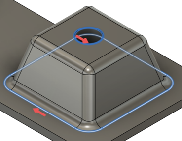
In this example, the strategy will offset passes from the two selected curves.
To machine areas that are unreachable by 3-axis machining, on the Multi-Axis tab, select the Use Multi-Axis checkbox to create a multi-axis geodesic toolpath.
Note: You require access to the Fusion Manufacturing Extension to create multi-axis toolpaths.If you selected Blend as the Type of Passes, on the Passes tab, you can select the Smooth Stepovers checkbox to intermediate curves between drive curves. This option helps to create smoother, more adaptive stepovers that reduce sharp corners, improve surface finish, and produce a more even toolpath.
Click OK.
The toolpath is generated.