Generate a Rotary Parallel toolpath
This feature is part of an extension. Extensions are a flexible way to access additional capabilities in Fusion. Learn more.
On the Manufacture workspace toolbar, click Milling > Multi-Axis > Rotary Parallel.
The Rotary Parallel dialog opens.
On the Tool tab, click Select to pick a tool. If you have not created a tool to use, In the left panel of the dialog, from the Fusion Library, pick a tool from the Sample Tools library.
Tip: ball type end mills are best suited for the Rotary finishing toolpaths.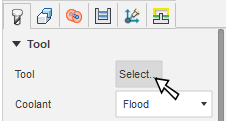
Set the orientation of the rotary axis. In the Geometry tab, select an option from the Orientation drop-down menu. For example, select Setup X Axis if you have set the X axis of your Setup to match the rotary axis in your machine tool.
Tip: Mouse over a parameter for more information.Set the rotary axis location by selecting an option from the Origin drop-down menu. For example, if you have set the origin of your WCS in your Setup to match the center of the rotary axis in your machine tool, then select Setup WCS origin.
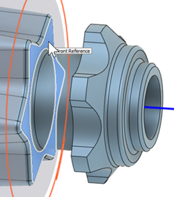
From the Front Mode drop-down list, select Stock front, Stock back, Selection, Model front, Model back, or Origin (absolute) as the front boundary to specify where the toolpath should start. If you want to select a face on your model from the canvas, choose Selection then click a face on the model on the canvas.
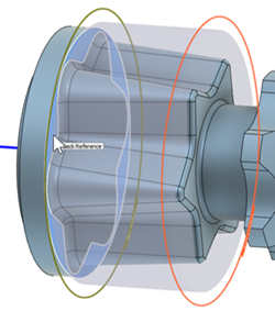
From the Back Mode drop-down list, select Stock front, Stock back, Selection, Model front, Model back, or Origin (absolute) to specify where the toolpath should end. If you want to select a face on your model from the canvas, choose Selection then click a face on the model on the canvas.
In the Passes tab, in the Rotary Passes group, select Spiral, Line, or Circular from the Style drop-down menu.
For a selection of Spiral or Circular, in the Passes group, enter a Stepover distance. If you selected Line, enter a Stepover angle.
Optional steps:
To avoid cutting with the center of a ball-nosed tool, in the Rotary Passes group, enter a Tool Offset distance.
To reduce the NC program size, enable Smoothing and enter a Maximum Point Spacing distance.
To machine a sector of the part, in the Geometry tab, enable the Set Angular Limits group. You can use angular limits only with the Line and Circular style of passes.
If you are using Collision Avoidance, on the Tool tab, you must specify Shaft & Holder clearances.
Click OK.
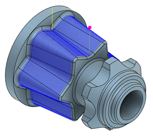
The toolpath is generated.
Watch the video below to see how to apply the Rotary Parallel toolpath.