Rotary Parallel milling strategy
This feature is part of an extension. Extensions are a flexible way to access additional capabilities in Fusion. Learn more.
The Rotary Parallel strategy is a finishing operation that uses the 4th axis on your machine tool to cut parts where continuous rotary motion is beneficial. It is best used when machining revolved parts, or any part with a centerline axis. The Rotary Parallel strategy generally creates 360° motion, but you can also specify an angular range to machine a limited section of your part. Depending on your part and machine tool, choose between the Spiral, Line, or Circular rotary toolpath style.
Choice of toolpath style
The style you choose depends on the model. In the example below, there is a large step on the part as you transition from the top of the bottle to its neck.
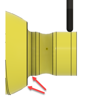
If you choose a Circular or Spiral style toolpath for the area that has the step, the tool may not cut the surface of the large step as it moves from one machining pass to another. The tool doesn't machine the surface because the model transitions from the beginning of the step to the end of the step in a smaller distance than the tool Stepover distance.
Circular-style toolpath does not machine the step
Instead, in this scenario, choosing a Line style toolpath provides a better result.
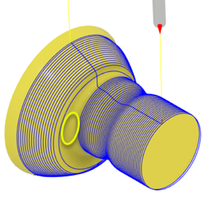
Spiral
Use the Spiral-style toolpath to machine the part in a continuous cut. To get a clean finish, a full circle is cut at the two ends. The Spiral-style toolpath is suited for simultaneous 4-axis machining as it generates a continuous toolpath, which gives a superior surface finish when compared to Circular.
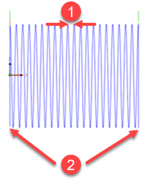
Spiral style side view
1 - Stepover distance
2 - Circle cut at two ends with a spiral style in between
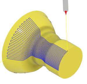
Line
Use the Line-style toolpath to move the tool along the rotary axis in 2 axis motion. The rotary axis is incremented on the short link between passes.
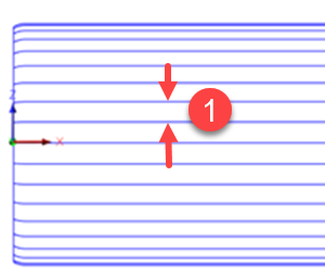
1 - Angular stepover
If your machine tool is not capable of simultaneous 4-axis machining, you can use the Line style toolpath for 3.5 axis machining. For example, a 4-axis machine has X, Y and Z-axis as the primary axes, plus an indexing table, designated as an A-axis. The indexing table is used for positioning the part, but it cannot rotate simultaneously with the motion of the primary axes.
If your rotary table is capable of simultaneous motion, you can still use the Line style toolpath if the rotary table does not have the indexing accuracy you require. At the end of each machining pass, the Line style indexes (small angular movement) the rotary table by the angular Stepover amount.
Circular
Use the Circular-style toolpath to rotate the part with the tool at a fixed position, effectively machining a cross-section. The tool then moves to machine the next cross-section by the Stepover distance. Choose the Circular-style over the Spiral-style if you do not want to machine around your part by over the full 360°.
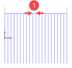
1 - Stepover distance
Tool offset
When using cutting tools such as a ball-nosed tool, you may want to avoid cutting with the center of the tool as the cutting speed of the tool at the center is much slower than the speed of the tool on its outer edge.
Cutting with the edge of the tool instead of its center increases the life of the tool and improves the surface finish of the part you are cutting.