Polar machining
Generally, polar machining is a 3-axis toolpath type. For supported toolpaths, the Multi-Axis tab lets you specify whether motion uses rotation on the machine C-axis instead of linear motion on the X or Y axis. This prioritizes table rotation over a limited linear axis when the machine cannot reach the entire part with standard 3-axis moves.
A polar toolpath looks like a 3-axis toolpath with the tool axis in Z, but uses rotations about the machine's rotational axis instead of X and Y motion. Polar machining is most useful when travel in X and Y is limited but the machine can rotate the table about Z to reach more of the part.
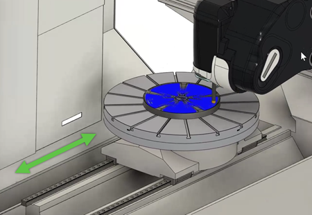
Limited machine travel in Y
On machines with limited Y-axis travel, the head can reach its travel limit before the tool can access the full part. Rotating the C-axis instead of moving along Y can remove that restriction and let you machine the entire part. You can also machine larger parts on the machine bed than would otherwise be possible with linear motion alone.
3-axis toolpaths in a mill/turn setup
For 3-axis toolpaths in a mill/turn setup, new options on the Multi-Axis tab help keep motion within the machine's travel limits:
- Use Rotations to Fit Limits — Allows a rotational move before the toolpath starts so the setup reaches a valid starting position within the machine's linear travel limits.
- Allow Polar Moves — When a single rotation is not enough, allows the post processor to convert the toolpath to polar moves to reach areas that linear motion cannot. If any linear move would exceed the travel limits, polar moves are used for the entire toolpath.
If all areas of the part are reachable with linear 3-axis motion, or become reachable after one rotation before the toolpath, the toolpath stays a standard 3-axis toolpath.
When Allow Polar Moves is selected, specify Polar Mode and, when In computer is selected, Polar Line Angle.
Polar machining type
Select Polar from the Machining Type group when polar moves should always be applied instead of linear XY motion. The Polar Machining group appears with Mode and Line Angle settings.
- Prefer in control — Uses polar cycles on the control when supported (such as G12.1). Standard 2D profiles including arcs can produce polar interpolated moves on the machine, and you can use toolpath radius compensation. If the control does not support polar cycles, the post processor uses In computer.
- In computer — Outputs arcs with linearized and C-axis moves when the control does not support polar cycles. You can view machine motion in simulation.
Line Angle
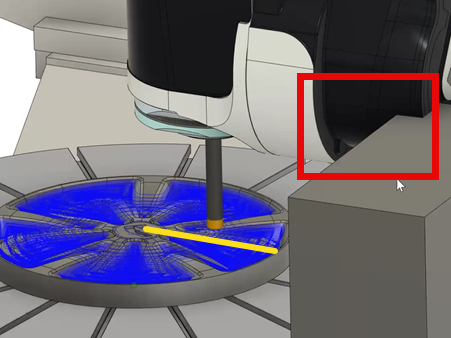
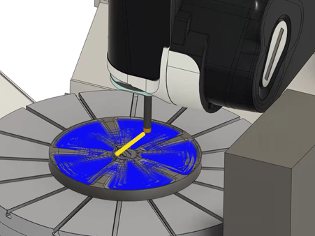
The Line Angle parameter (or Polar Line Angle when you use Allow Polar Moves with 3-axis machining) can improve cutting visibility for the operator and help avoid collisions, especially on machines with asymmetric heads that have obstacles such as coolant pipes. By adjusting the line angle, you shift the direction of linear motion from alignment with the Y axis toward the X axis (measured counterclockwise from the setup WCS X-axis at the rotary center). This lets the tool reposition and rotate in a direction that avoids obstacles, which can result in smoother and safer machining and reduce the risk of damage to the tool and workpiece.
For example, when a cobot or robot loader is near the work area, changing the line angle can move the cutter path away from the loader and help avoid collisions.
Specify a line angle when Mode or Polar Mode is In computer.
In the example below, the line angle is set to 0 degrees. This causes a collision between the head and a nearby object:
Changing the line angle to 90 degrees repositions the tool and part (rotates the line 90 degrees counterclockwise starting from the X-axis of the WCS) to avoid the collision:
Polar linking moves
When Polar is the machining type, linking moves can also use polar motion. On the Linking tab, select Use Rapid Links with Polar Motion when you want rapid links to follow rotary motion around the specified Center of rotation instead of linear XY moves. This can produce smoother transitions on table-type machines.
Post processor support
Your post processor must support polar machining output. If the post processor is not configured for polar moves, machine simulation can show non-polar motion even when polar options are enabled in the toolpath.