Control the display of inspection results for geometric fitting
Import the machine-generated results file from a Probe Geometry operation used for geometric fitting.
In the Browser, under the Results node, ensure that the inspection results are visible.
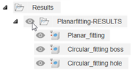
Right-click a folder containing the inspection results and choose Geometric Fitting Display Options.
In the Geometric Fitting Display Options dialog, select the Measured Points checkbox to display the measured points where the probe inspected the geometric features.
More options become available to control the display of the results on the canvas.
Optional steps:
- To show or hide points that are below, within, or above the specified form tolerance, click the Filter Points buttons.
- To change the magnitude of the point indicators and the form tolerance bounds for each measured geometric feature, click and drag the Scale slider.
- To display the allowable deviation of each geometric feature from its ideal form, select the Form Tolerance Limits checkbox.
Click OK.
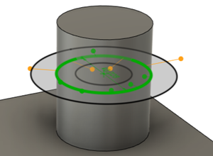
Geometric fitting of a circle on a boss.
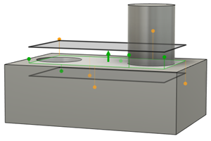
Geometric fitting of a plane on a face.