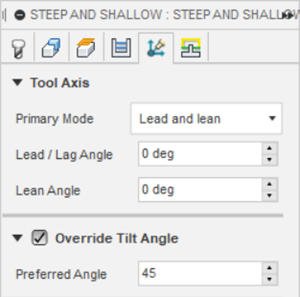
Tilt Angle override
This feature is part of an extension. Extensions are a flexible way to access additional capabilities in Fusion. Learn more.
When using a non-vertical Primary Mode setting, the tool axis may tilt excessively as it tries to machine a certain area of your model. Excessive tilting of the tool axis can result in an undesired surface finish.
For example, consider a toolpath that machines a surface that is constantly tilting over a changing surface. The tool axis tilts excessively as it tries to machine the surface, which results in a poor surface finish.
Excessive tool axis tilting with Lead = 0 and Lean = 0
To maintain a high-quality surface finish, it may become important to lock a rotational axis of your machine tool to avoid the tool tilting excessively. Selecting the Override Tilt Angle checkbox and specifying a Preferred Angle results in locking a rotational axis of the machine tool, which means the tilting motion of the tool is reduced and the tool axis stays at the Preferred Angle away from the Tool axis reference.
How Override Tilt Angle works
When you select Override Tilt Angle and specify a Preferred Angle, the preferred angle you specify is measured from the Tool Axis Reference. The reference can be the tool orientation Z axis or the setup Z axis.
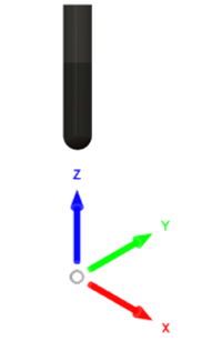
The Preferred Angle can be thought of as a conical boundary around the Tool axis reference. A Preferred Angle of 45 degrees creates a conical boundary whereby the tool can sit anywhere on the edge of this boundary, as long as the tool is 45 degrees away from the Tool axis reference.
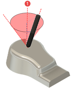 |
| 1 - Tool axis reference |
To determine where the tool sits on the conical boundary, non-vertical Primary Mode settings provide an initial position, after which the tool axis moves to align with the edge on the conical boundary that it is closest to.