Tool Axis Smoothing
This feature is part of an extension. Extensions are a flexible way to access additional capabilities in Fusion. Learn more.
A machine tool uses one or more rotary axes to provide 3-axis plus (such as 4-axis and 5-axis machining) capability. The rotary axes are used when machining using a multi-axis toolpath.
Enter a Smoothing Distance to specify the distance over which any sudden rotary axes motion can be smoothed.
To achieve a smooth rotary motion, as the tool transitions over the smoothing distance, the maximum angle by which the tool axis can deviate from its Primary Mode is set by the Smoothing Angle. Generally, the larger the Smoothing Distance and Smoothing Angle, the more gradual the transition, and therefore the better the surface finish.
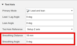
Smoothing Distance
The Smoothing Distance is the distance before and after an area of a model where the machine's rotary axes require movement to change the tool's tilting angle or direction.
An example of when smoothing might occur is an outer corner of a part, as shown in the animation below. The yellow lines throughout the toolpath segment represent a change in the tool axis direction or tilt angle.
In the animation below, increasing the Smoothing Distance means that the tool has more distance over which to adjust its motion to arrive at a suitable orientation for the corner.
 |
 |
| Smoothing Distance = 5 mm | Smoothing Distance = 50 mm |
| Sudden transition at corner | Smoother transition before and after corner |
Smoothing Angle
The Smoothing Angle is the maximum angle the tool axis can deviate from its Primary Mode to provide smooth transitions while moving along the smoothing distance. The Smoothing Angle takes effect when there is a change in the machine's A and C, or B and C axes.
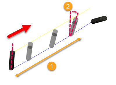
In the toolpath segment example below, the tool has an initial and final orientation (controlled by the Primary Mode setting). Conceptually, If is no smoothing applied at all, the tool axis will perform a sudden angular change between position 2 and position 3.
When there is a sudden angular change (between position 2 and 3), the axes of the machine tool rapidly accelerate and decelerate, which causes the tool to dwell on the part, resulting in an undesirable surface finish.
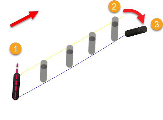
1 - Initial orientation because of a Primary Mode setting.
2 - Position of tool before a sudden change in tilt angle.
3 - Final orientation because of a Primary Mode setting.
The tool axis adjusts itself over the smoothing distance and deviates by a maximum smoothing angle from its initial orientation.
 |
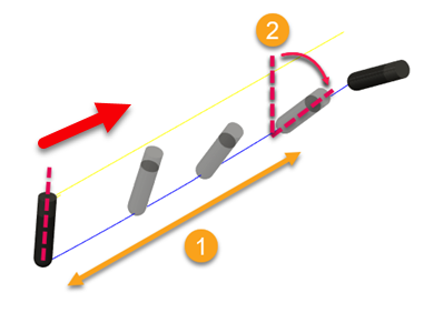 |
| 1 - Smoothing Distance = 30 mm | 1 - Smoothing Distance = 30 mm |
| 1 - Smoothing Angle = 5 deg | 1 - Smoothing Angle = 45 deg |
| Sudden transition | Smoother transition |