Part Alignment reference
This feature is part of an extension. Extensions are a flexible way to access additional capabilities in Fusion. Learn more.
Use the Part Alignment dialog to specify the type of transformation that Fusion can use to calculate a part alignment.
Manufacture > Inspection > Probing > Part Alignment 
Manufacture > Inspection > Probing > Live Part Alignment
The dialog contains the following settings:
Method
Specifies which axes are free to be transformed in the part alignment. Choose a method that is supported by your machine and post processor.
Select:
2 Axis to enable rotation about one rotary axis and optional translation along the axis.
3 Axis to enable translation along one, two, or three linear axes.
4 Axis to enable translation along all linear axes and rotation about one rotary axis.
5 Axis to enable translation along and rotation about all axes.
For example:

Rotary Axis
If you selected a Method of 2 Axis, specify the direction of the rotary axis used when calculating the part alignment. Together with Rotary Origin, this defines the axis about which the part can rotate.
Rotary Origin
If you selected a Method of 2 Axis, specify the point that the rotary axis passes through when calculating the part alignment. Together with Rotary Axis, this defines the axis about which the part can rotate.
Lock Translation Along Axis
If you selected a Method of 2 Axis, control whether translation can happen along the rotary axis.
Select the checkbox to restrict the alignment to rotation about the axis only. Deselect the checkbox to allow translation along the rotary axis in addition to rotation about the axis.
Allow Translation Along X/Y/Z Axis
If you selected a Method of 3 Axis, select the checkboxes to enable translation along the X, Y, and Z axes.
Deselect the checkboxes if your CNC machine or post processor is limited or you want to restrict the translation.
Axis of Rotation
If you selected a Method of 4 Axis, select the axis that can be rotated.
Results for Calculation
If you have already imported inspection results and want to use them to calculate the part alignment, manually select the inspection results in the Browser under the Results node.
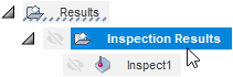
Otherwise, the part alignment is calculated when you click Get Results > Import Inspection Results and choose a machine-generated results file.