Setup tab (milling and cutting) reference
This section covers the parameters that define the stock size, stock shape, WorkCoordinate System (WCS) axis orientation and part zero.
Manufacture toolbar, click Setup > New Setup ![]() .
.
If you are using a Machine Definition, select your machine. Selecting the machine defines the Operation Type.
The information below assumes you have selected a Milling or a Cutting, Operation Type.
For more information, watch the Set up a collaborative project for a distributed design video.
Work Coordinate System (WCS) - Milling & Cutting
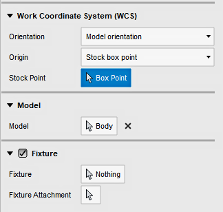
The Work Coordinate System (WCS) specifies the global coordinate system in which the post processed toolpath is output. The WCS defaults to the model orientation.
 |
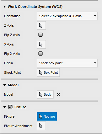 |
| Model Orientation. | Select Z axis/plane & X axis. |
Orientation
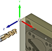
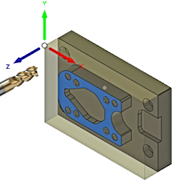
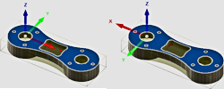
The Orientation allows you to set the working XY plane and the Z spindle axis orientation. The drop-down menu provides the following options to define the setup orientation of the X, Y, and Z WCS axes. The Z should always point away from the face you plan on machining.
 |
 |
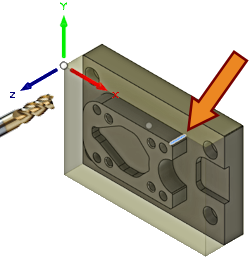 |
| Z Orientation. | Select perpendicular face | Select parallel edge. |
- Model orientation - Uses the orientation of the current part for the WCS orientation.
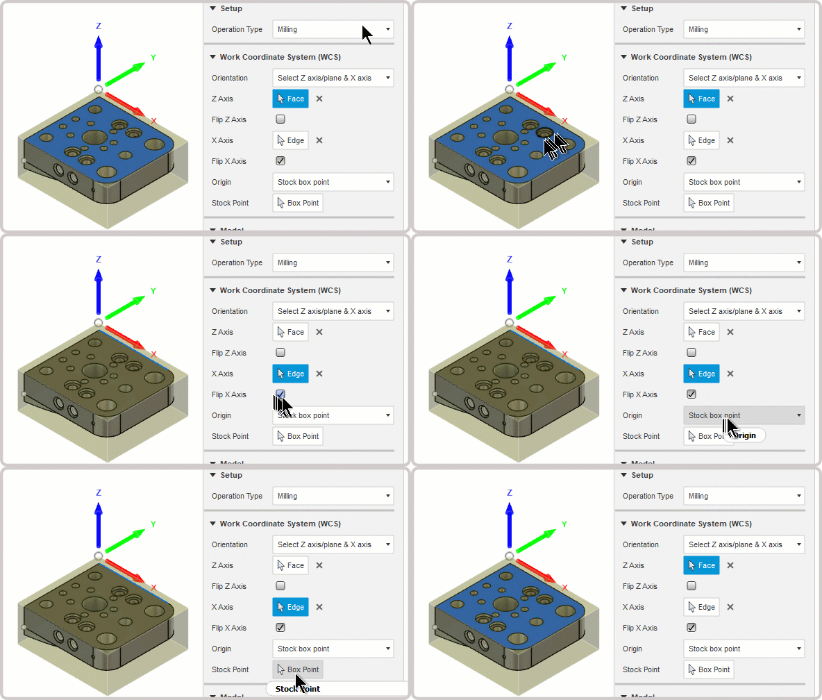
- Select Z axis/plane & X axis - Select a face or an edge to define the Z axis and another face or edge to define the X axis. Both the Z and X axes can be flipped 180 degrees.
- Select Z axis/plane & Y axis - Select a face or an edge to define the Z axis and another face or edge to define the Y axis. Both the Z and Y axes can be flipped 180 degrees.
- Select X & Y axes - Select a face or an edge to define the X axis and another face or edge to define the Y axis. Both the X and Y axes can be flipped 180 degrees.
- Select coordinate system - Sets the WCS orientation for the setup from a defined user coordinate system in the model. This uses both the origin and orientation of the existing coordinate system. Use this option if your model does not contain a suitable point and plane for your operation.
Select a Face or Edge to set the axes.
|
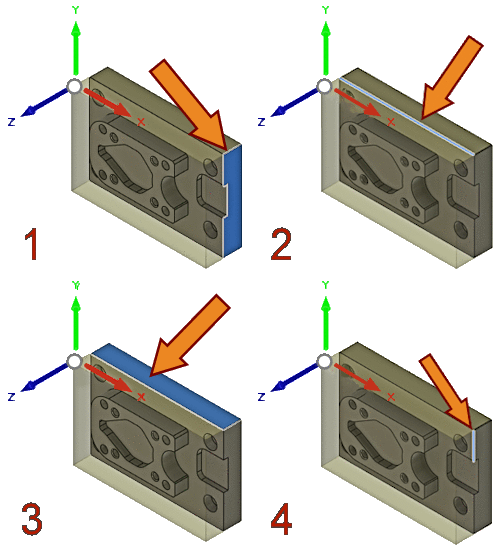 |
 Flip Z Axis |
 Flip X or Y Axis |
 |
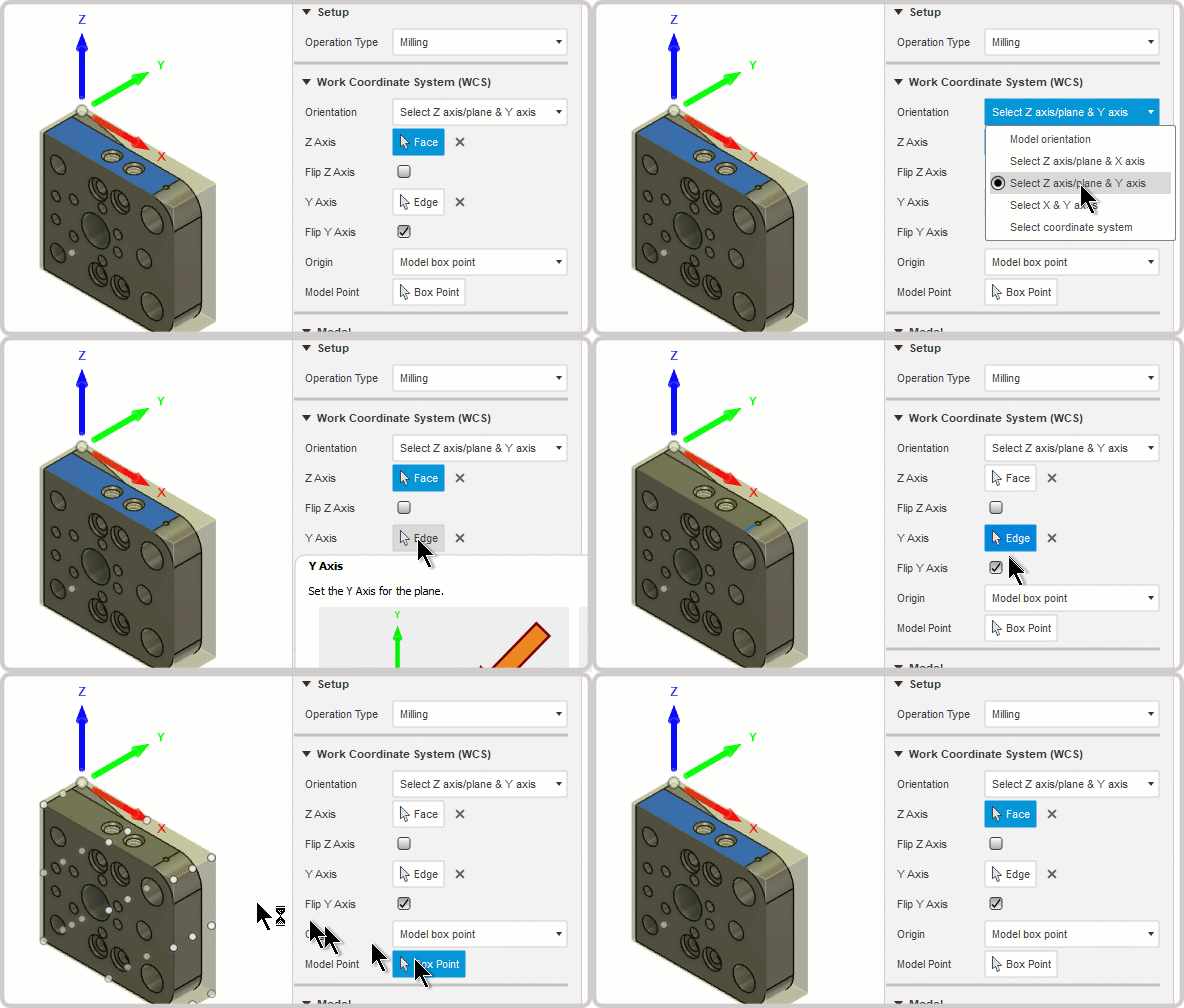 |
| Select Z axis/plane & X axis. | Select Z axis/plane & Y axis. |
Origin
The Origin allows you to set the reference for defining part zero. The drop-down menu offers the following options for locating the WCS origin:
- Model origin - Uses the coordinate system origin of the model for the WCS origin.
- Selected point - Select a vertex or an edge for the WCS origin.
- Stock box point - Select a point on the stock bounding box for the WCS origin.
- Model box point - Select a point on the model bounding box for the WCS origin.
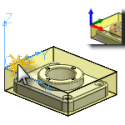
Stock box - Model box Point
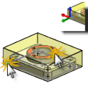
Specifies the XYZ zero origin of the machining plane.
 |
 |
||
| Select lower corner origin | Select upper corner origin |
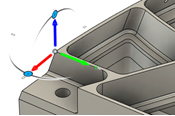
Accessibility analysis
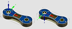
You can assess which areas are accessible to the tool given the currently set orientation using Accessibility Analysis
 |
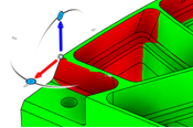 |
| Accessibility analysis off | Accessibility analysis on |
Model
The model defines what is being machined. By default, all the models on the canvas are automatically selected. If you have multiple models representing multiple parts, you can individually select which models you want included in the setup.

Fixture
You can also specify any model as a fixture. A fixture is a structure that holds or supports the workpiece during machining, for example, a vice, a clamp, or a chuck. Collisions with fixtures are highlighted during stock simulation.