Machines for manufacturing
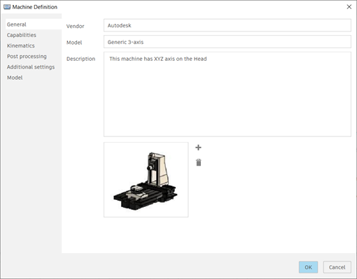
A machine definition, also known simply as a machine, is a collection of settings that describe the physical and operational characteristics of a CNC machine or additive printer. By using machine definitions, you can optimize your manufacturing processes and simulate machine movements with greater accuracy.
A machine definition includes a range of settings that determine how the machine operates and what it can do. For CNC machines, these settings include the machine’s capabilities, such as milling, turning, or cutting, and its kinematics.

While using a machine definition is not required in milling, turning, or cutting setups, it can improve the manufacturing process. Operations in a setup that use a machine definition are specific to that machine, optimizing them for the capabilities of the CNC machine. In additive setups, using a machine definition is required.
Finding and storing machine definitions
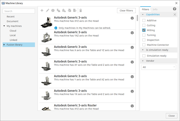
Machine definitions are stored in the Machine Library, which contains various folders for different sources, including the Recent, Document, and Fusion Library folders and the My Machines subfolders.
The Fusion Library folder offers a wide range of predefined machine definitions that you can directly copy and use. If a machine definition does not match your physical machine, you can edit it or create one to meet your specific needs. The My Machines subfolders allow you to store your machine definitions locally or in the cloud.

Linking post processors
A post processor, also known as a post, converts manufacturing operations into a language that a CNC machine can understand. This action is known as post processing or posting. The output from post processing is an NC file, usually in the form of G-code. The NC file is exported from Fusion, transferred to the CNC machine's controller, and then run on the CNC machine.
For CNC machines, you can link a post processor to a machine definition. When you link a post processor, the NC code generated when you post process operations is optimized for the capabilities of the specific machine.
Enhancing simulation with machine models
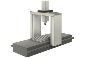
A machine model is a Fusion design file that contains the 3D model of a CNC machine. By linking a machine definition to a machine model, you can visualize the movements of the CNC machine during machine simulation. This provides a more realistic representation of how the physical CNC machine moves when running NC code. And it helps you identify potential issues, such as collisions, before running the NC code on the physical CNC machine.

Machine definitions in the Fusion Library folder typically have a linked machine model. However, you can often get a machine model from your CNC machine’s manufacturer to ensure an accurate representation of your machine’s geometry. Alternatively, you can create your own machine model, customizing it as needed. If you want to set up a machine model, use the Machine Builder.
Editing machine definitions and machine models
Changes to a machine definition are specific to the instance being edited.
When you edit a machine definition in a My Machines subfolder (for example, Local, Linked, or Cloud), these changes affect only this instance of the machine definition and do not impact instances in the Document folder. Likewise, when you edit a machine definition in the Document folder, these changes affect only this instance of the machine definition and do not impact instances in other documents or in the My Machines subfolders.
A machine model can be linked to a machine definition. You cannot edit a machine model from a machine definition that is stored in the Document folder. However, you can edit a machine model from a machine definition that is stored in a My Machines subfolder.
If you edit a machine model from within a machine definition in a My Machines subfolder, a notification appears in the active document to inform you that the machine model is out of date. To update only the machine model, right-click the machine definition in the Browser and select Update Machine Model.

Multi-axis settings in machine definitions
For CNC machines with four or more axes, you can specify multi-axis settings in its machine definition. These settings allow you to optimize the machine’s performance and avoid potential issues during machining. Examples of things you can configure include:
Retract and reconfigure settings, which enable the machine to automatically move and avoid overtravels that occur when the machine goes beyond its physical limits.
Multi-axis feedrate methods to ensure smooth and efficient tool movements.
Singularity management settings to optimize simultaneous multi-axis toolpaths and avoid potential issues that may arise from singularities, which are points where two or more tool axes align and limit the machine’s range of motion.