Work with the gauge length of tool holders and tool assemblies
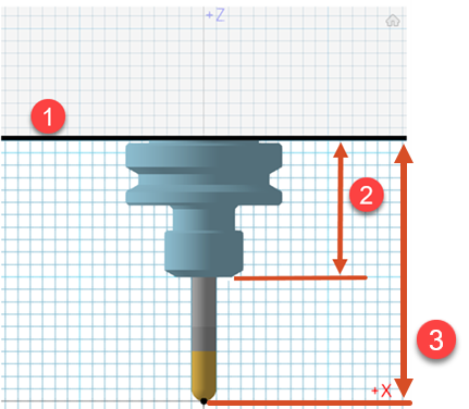
A gauge line (1) is a reference line for measurement. It represents the attachment point of the holder to the spindle. The gauge length of a tool holder (2) represents the total height of segments of a holder below the gauge line. The gauge length of a tool assembly (3) is the distance between the gauge line and the tip of the tool.

Define the gauge line of a holder to accurately represent the holder in the spindle or tool block. You can also compare the gauge length of the holder in Fusion to the measured gauge length of the holder or tool assembly.
Define the gauge length of a tool holder
On the Manufacture workspace toolbar, on any tab, click Manage > Tool Library
 .
.In the Tool Library, in the left panel, in the Documents, Local, or Cloud folder, select the library that contains the holder.
Click Edit Tool
 .Tip: If a holder does not exist, click New Tool
 and choose Holder to create a tool holder.
In the dialog that opens, click the Holder Geometry tab.
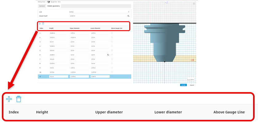
Click Add Segment
 or Delete Segment
  as needed to add or delete segments of the tool holder.
 Note: The calculated Gauge Length updates as you add or delete segments.
Optional steps:
To exclude a segment from the calculation of the Gauge Length, select its Above Gauge Line checkbox.
To change the calculated Gauge Length to a user-defined length, type a new value in the box.
Note: The Gauge Length must be a positive value and must not exceed the total height of all segments.
Edit the gauge length of a tool assembly
After you create a holder, you can copy and apply the holder to another tool.
Make sure to check and edit, if needed, the gauge length of the tool assembly and the tool's length below the holder.
On the Manufacture workspace toolbar, on any tab, click Manage > Tool Library
 .
.Select the tool where you copied and applied the holder.
Click Edit Tool
 .Note: You can edit tools in the Documents, Local, and Cloud folders.
In the dialog that opens, click the Cutter tab.
In the Tool Assembly group, edit the Gauge Length.
In the Geometry group, edit the Length Below Holder for the current tool.
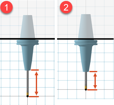
In the 3D tool preview, verify the tool assembly.

A tool assembly after editing the Gauge Length (1). A tool assembly after editing the Gauge Length and the Length Below Holder (2).