Set a tool's orientation from model geometry
On the dialog of the operation you are using, in the Multi-Axis tab, expand the Tool Orientation group.
From the Tool Orientation drop-down list, select an option. The steps below describe what to do when you select the commonly used option Select Z axis/plane & X Axis.
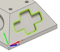
With the Z Axis button active, select a face containing the machining area. Selecting a face sets the axis perpendicular to the face.
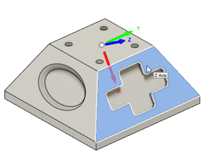
(Optional) To flip the Z-axis direction, select Flip Z Axis.
With the X Axis button active, select an edge to define the X-axis direction. Selecting an edge sets the axis parallel to the edge.
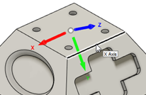
(Optional) To flip the X-axis direction, select Flip X Axis.
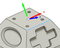
(Optional) To change the location of the origin, select an option from the Origin drop-down list, then, depending on the option, select a point on the canvas as the location of the origin.
(Optional) to assess which areas are accessible to the tool given the currently set orientation, next to Accessibility Analysis, click Preview.
Turn, Tilt, Align to View, and Surface Normal
In addition to the steps described above, use Turn, Tilt, Align to View, and Surface Normal options to help set the tool orientation, particularly on parts where there is limited geometry to reference from.
Align to View: Aligns the tool orientation to the current viewing direction.
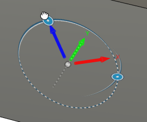
Tilt and Turn: Adjust the tool orientation using the manipulators on the canvas.
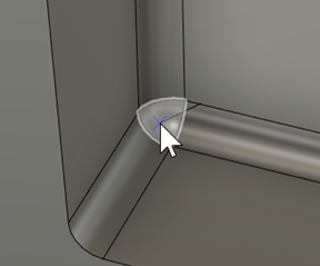
Surface Normal: Aligns the tool perpendicular at the selected point on the surface.