Activity 1: Set up the part on the machine's build platform
In this activity, you open the file containing the part, then create a setup selecting a build machine and a print setting. You then position the part on the build platform and create supports for some of the part's surfaces. When creating supports, the aim is to restrain deformation and conduct heat away from the fusion layer to the build platform.
Prerequisites
The Design workspace is open.
If necessary, switch from inches to millimeters.
In the Browser, to the right of Units, click Change Active Units.
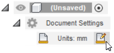
In the Change Active Units dialog, select a Unit Type of Millimeter.
Click OK.
Steps
Open the Additive Process Simulation part.
- If necessary, on the Application bar, click Show Data Panel
 .
. - In the Data Panel, under Samples, double-click CAM Samples > Additive Manufacturing > MPBF > Additive Process Simulation.
- Close the Data Panel.
- If necessary, on the Application bar, click Show Data Panel
On the Design workspace toolbar, from the Workspace menu, select Manufacture.
Create a setup selecting the Renishaw AM 250 machine and the RenAM250 Inconel In65-1118-Q 60 micron print setting.
On the Manufacture workspace toolbar, click Additive > Setup > New Setup
 .
.The Setup dialog opens.
Next to Machine, click Select.
The Machine Library opens.
In the left panel, ensure that the Fusion Library folder is selected.
In the right panel, on the Filters tab, ensure that Capabilities is set to Additive and Technologies is set to MPBF.
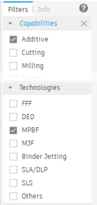 Note: MPBF machines are available only with the Fusion Manufacturing Extension.
In the middle panel, find and select Renishaw AM 250, then click Select to close the Machine Library.
In the Setup dialog, next to Print Settings, click Select.
The Print Setting Library opens showing a range of possible materials to use for the simulation.
In the left panel, ensure that the Fusion Library folder is selected.
In the right panel, on the Filters tab, ensure that Technologies is set to MPBF.
In the middle panel, find and select RenAM250 Inconel In625-1118-Q 60 micron, then click Select to close the Print Setting Library.
Ensure that the Arrangement checkbox is selected.
Click OK.
A Setup node is added to the Browser and the Additive Arrange dialog opens.
Position the part directly on the build platform.
In the Additive Arrange dialog, enter a Platform Clearance of 0.
Click OK to automatically arrange the part on the machine's build platform.
The Additive Arrange dialog closes.
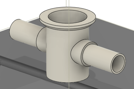
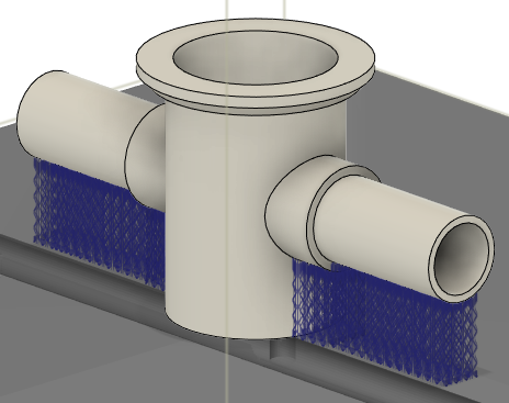
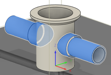
Add volume supports for the part's two horizontal pipes to prevent deformation of these surfaces from the heat of the build process.
On the Manufacture workspace toolbar, click Additive > Supports > Volume Support
 .
.The Volume Support dialog opens.
Ensure that Selection is active.
On the canvas, zoom in to the part and click the outer surfaces of the horizontal pipes.
In the dialog, click OK.
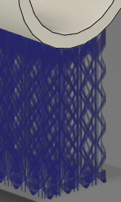
Supports using a complex lattice structure are generated under the pipes and a Supports node is added to the Browser.

Note the complex lattice structure of the supports. Meshing these directly will result in a very dense mesh and a long simulation time. In the next activity, a more viable solution is demonstrated.
Activity 1 summary
In this activity, you opened the file containing the part, created a setup selecting a build machine and a print setting, positioned the part on the build platform, and then created some supports.