Activity 2: Create a Process Simulation study
In this activity, you create a Process Simulation study for the part, refine the mesh settings for the study, choosing a balance between accuracy and speed, then generate a preliminary finite element analysis (FEA) mesh. The mesh is a mathematical representation of the part made up of elements and is where the process simulation is solved. By generating a preliminary mesh, you check its integrity before you solve the Process Simulation study.
Prerequisites
- Activity 1 is complete.
Steps
Create a Process Simulation study for the part.
On the Manufacture workspace toolbar, click Additive > Process Simulation > Study
 .
.The Study dialog opens.
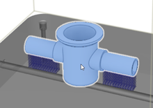
With Target Body active, on the canvas, click the part.
In the dialog, click OK.
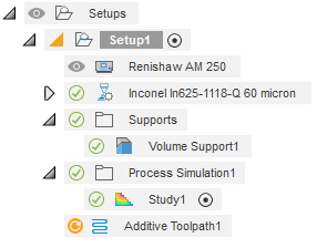
A Study node is added to the Browser and the Solve dialog opens.
Refine the mesh settings for the study by setting the Layers per Element to 15, the Coarsening Generations to 2, and the Max. Adaptivity Level to 5.
In the Solve dialog, in the Solve Accuracy group, click Settings
 .
.The Study dialog opens with a slider to control the balance between accuracy and speed in the solve process.
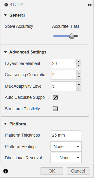
In Advanced Settings, ensure that Auto Calculate Support Volume Fraction is selected and set the following values to choose a coarse mesh that generates quickly:
- Layers per element: 15
- Coarsening Generations: 2
- Max. Adaptivity Level: 5
Tip: Place the pointer over each setting for a few seconds to see a tooltip that explains the range of values for the setting and the effects on the mesh. These make more sense when you examine the mesh.Click OK.
The Study dialog closes.
Generate a preliminary mesh.
In the Solve dialog, in the FEA Mesh group, click Check Mesh
 .Note: An orange exclamation mark
 next to FEA Mesh means that the mesh has not yet been checked.
The CAM Task Manager opens and displays progress of the mesh generation. When completed, a Results contextual environment replaces all the existing tabs in the Manufacture workspace.

In the CAM Task Manager, when progress is 100%, click Close.
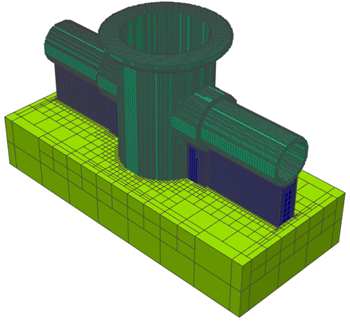
A mesh of the part is shown on the canvas of the Results contextual environment. The mesh is colored by structure type. This mesh is the same mesh you will use in the solve process. By generating it in advance, you can examine the integrity of the mesh and decide whether to correct any problems before solving.

The mesh displays several important structural features:
The fine lattice supports, instead of being meshed directly, which would require numerous, small elements, are instead homogenized. Homogenization is the process of modeling a fine patterned feature with a volumetric representation. Key material properties are scaled by the Volume Fraction, which is the ratio of the actual support material volume to the volume of the representative shape.
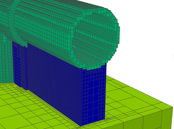
Areas of fine detail, such as the curved pipes, are built with very small voxels, or elements, to capture the geometric detail. In areas of less detail, such as the core of the support structure and the build platform, the elements are coarsened and combined to form larger elements that can be solved much faster.
At a minimum, meshes should have two elements through every cross-sectional area, to allow the mesh to deform. This is easiest to check by referencing the thinnest section and ensuring it has at least two elements.
The mesh is colored by structure type, where supports are blue, the part is cyan, and the build platform is green. Any unsupported elements are red. Unsupported elements are those elements not connected to the build platform. Often, unsupported elements occur when the mesh is too coarse to capture connecting features, or when there is a lack of support structures.
For more information about mesh settings, see Mesh Settings and Finite Element Meshing for Additive Processes in the Netfabb Help.
Activity 2 summary
In this activity, you created a Process Simulation study for the part, refined the mesh settings for the study, then generated a preliminary mesh to check its integrity before you solve the Process Simulation study.