Generate a multi-axis Swarf toolpath
This feature is part of an extension. Extensions are a flexible way to access additional capabilities in Fusion. Learn more.
On the Manufacture workspace toolbar, click Milling > Multi-Axis > Swarf.
The Swarf dialog opens.
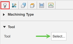
On the Tool tab, click Select to pick a tool. If you have not created a tool to use, in the left panel of the dialog, from the Fusion Library, pick a tool from the Sample Tools library.
Tip: You can use flat, bull, or ball end mills for Swarf toolpaths as long as the flute is long enough to cover the machining face.
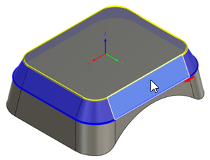
On the Geometry tab, from the Drive Mode drop-down list, select the Contours or Faces option to determine how to drive the toolpath. The geometry can be swarf machined as long as there is a flat edge between what is driving the toolpath.
From the Selection Mode drop-down list, specify how you want to select what drives the toolpath.
Tip: Mouse over the Selection Mode drop-down list for more information.
Image shown with Contours as the Drive Mode and Faces as the Selection Mode.
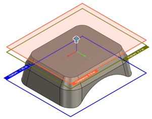
On the Heights tab, adjust the vertical area to machine in Z, by setting the Bottom Height of the cutting area.

On the Passes tab, change the Cutting Mode to determine how to machine down the sides of a part. By default, a single pass is generated. Different options in the drop-down list can provide multiple stepdowns if required.
Optional steps:
To tilt the tool towards or away from the part, enter a Sideways Tilt value.
To reduce the NC program size, increase the Maximum Tool Axis Sweep and Maximum Segment Length parameters.
On the Linking tab, to keep the tool down for longer, increase the Maximum Stay-Down Distance.
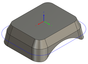
To change where the tool enters the part, in the Positions group, with Entry Positions active, select any point on the model that sits on an edge.
Click OK.
The toolpath is generated.
