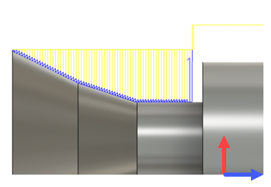
Generate a Turning Groove Roughing toolpath
On the Manufacture workspace toolbar, click the Turning tab > Turning > Turning Groove Roughing
 .
.The Groove Roughing dialog opens.
On the Tool tab, click Select to pick a tool. If you have not created a tool to use, in the left panel of the dialog, from the Tool Library, pick a tool from the Fusion Library.
Tip: ID grooving, OD grooving, or Face grooving tools from the Turning Tools (Inch) or Turning Tools (Metric) library are best suited for removing material with a toolpath like Groove Roughing. Select the library based on the units that you use.In the Tool Settings group, select a Spindle Rotation option.
Forward (clockwise) and Reverse (counter-clockwise) are relative to the main spindle while looking from behind the chuck. Ensure the spindle rotates towards the insert on the tool.
Note: This setting changes only the spindle direction and does not affect the tool orientation. Visually confirm simulation results and check the spindle M codes in the post-processed output before running code on a CNC machine.Select a Turning Mode option appropriate to the location of the groove on the model.
On the Geometry tab, define the toolpath area in the Z axis with a front and back boundary.
It is common to choose Selection from the Front Mode or Back Mode options to set the boundary. You can extend these selections by entering an Offset value.
On the Radii tab, adjust the area to machine in the X axis. Set the Outer Radius and Inner Radius to specify the outer and inner limits of the cutting area.
Optional steps:
- To exclude grooves from machining, on the Geometry tab, select Groove Suppression, then select the surfaces enclosing each groove.
- To control the cut direction, on the Passes tab, select a Direction option.
Click OK.
