Generate a Turning Profile Roughing toolpath
On the Manufacture workspace toolbar, click Turning > Turning > Turning Profile Roughing
 .
.The Profile Roughing dialog opens.
On the Tool tab, click Select to pick a tool. If you have not created a tool to use, in the left panel of the Tool Library dialog, pick a tool from the Fusion Library, the Turning Tools library.
Tip: A right handed tool is the most common selection for this toolpath.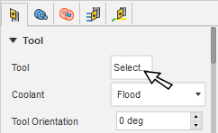
In the Tool Settings group, select a Spindle Rotation option.
Forward (clockwise) and Reverse (counter-clockwise) are relative to the main spindle while looking from behind the chuck. Ensure the spindle rotates towards the insert on the tool.
Note: This setting changes only the spindle direction and does not affect the tool orientation. Visually confirm simulation results and check the spindle M codes in the post-processed output before running code on a CNC machine.On the Geometry tab, you contain the toolpath area in the Z axis, with a Front and Back boundary. You can extend the selected Front Mode or Back Mode by entering an Offset value.
On the Radii tab, adjust the area to machine in X. Set the start point of a cut on the Outer Radius and the end point of a cut on the Inner Radius.
On the Passes tab, set the Maximum Depth of Cut to a value appropriate for your tool and material type.
Optional steps:
To prevent roughing in the undercut areas, adjust the Grooving parameters.
To machine multiple regions in one operation, select the Machine Multiple Regions checkbox.
Enable Even Depths of Cut if you want equal cut depths.
Enable Use Pecking to break longer cuts into multiple steps.
Enable Skip Wall Pass to skip the cusp cleanup move after every cutting move.
To lead into the part at an angle, in the Linking tab, enable Angled Entry and specify the angle, clearance, and feed values.
Click OK.
The toolpath looks as follows.
![]()
Roughing with Grooving set to Don't allow grooving.