Generate a Turning Trace toolpath
On the Manufacture workspace toolbar, click Turning > Turning > Turning Trace
 .
.The Trace dialog opens.
On the Tool tab, click Select to pick a tool. If you have not created a tool to use, in the left panel of the Tool Library dialog, pick a tool from the Fusion Library, the Turning Tools library.
In the Tool Settings group, select a Spindle Rotation option.
Forward (clockwise) and Reverse (counter-clockwise) are relative to the main spindle while looking from behind the chuck. Ensure the spindle rotates towards the insert on the tool.
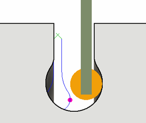
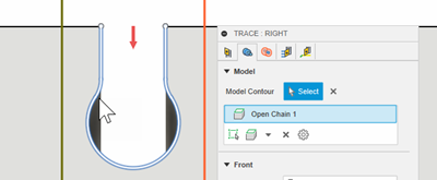
Note: This setting changes only the spindle direction and does not affect the tool orientation. Visually confirm simulation results and check the spindle M codes in the post-processed output before running code on a CNC machine.On the Geometry tab, select a model contour from the model or sketch to drive the toolpath.
You can contain the toolpath area in the Z axis, with a Front and Back boundary. You can extend the selected Front Mode or Back Mode by entering an Offset value.
On the Radii tab, adjust the area to machine in X. Set the start point of a cut on the Outer Radius and the end point of a cut on the Inner Radius.
On the Passes tab, from the Sideways Compensation drop-down menu, select an option to determine which side of the model contour to machine.
Optional steps:
- To perform a safer retract move back along the contour, select the Return on Curve checkbox.
- To have fixed directions for lead moves when Sideways Compensation is not set to Center, in the Linking tab, select Use Fixed Lead Direction.
- To cut with the back edge of a grooving tool, you can compensate for the tool width and check the back edge for gouges against the model by selecting the Compensate for Tool Width checkbox.
Click OK.