Drawing workspace reference
You can create drawings to document design assemblies and animations in the Drawing workspace in Fusion.
If you plan to reuse title blocks, borders, document settings, or sheet settings across multiple drawings, create a drawing template to save time and apply consistent standards. You can also create placeholder views and placeholder tables that automatically generate drawing views and part lists from the referenced design when you use the template to create a new drawing.
Access the Drawing workspace
Open a saved design in Fusion.
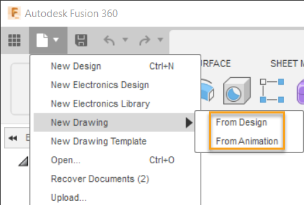
From the Application Bar, click File > New Drawing > From Design or From Animation.

The Create Drawing dialog displays.
Adjust the settings in the Create Drawing dialog, then click OK.
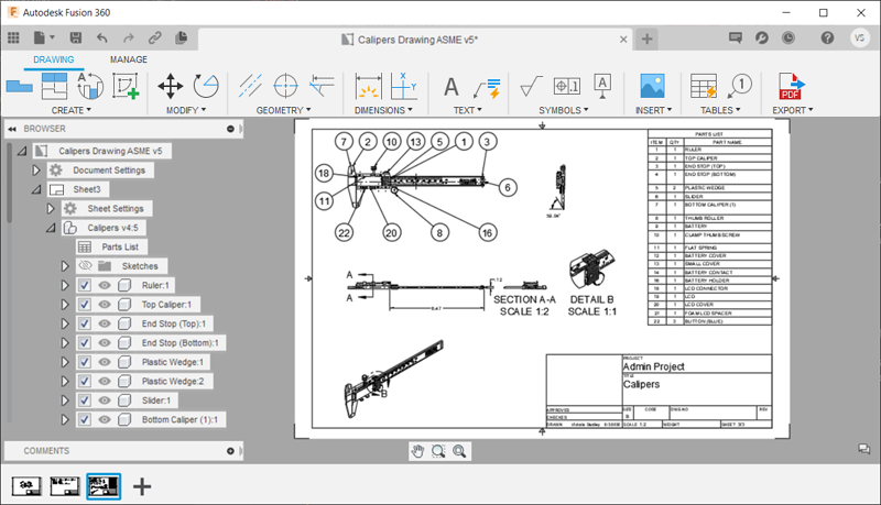
Fusion creates a new drawing and opens it in a new document tab, where the Drawing workspace is active.

Drawing tab
On the toolbar, the Drawing tab appears.
The Drawing tab is divided into panels:
- Create
- Modify
- Geometry
- Dimensions
- Text
- Symbols
- Insert
- Tables
- Export
Create panel
Select any of the commands in the Create panel to create new drawing views, broken views or sketch on the current sheet.
| Command | Description |
|---|---|
| Base View | Creates an orthographic base view of the design assembly. |
| Projected View | Projects orthographic views of the design assembly, relative to a parent view. |
| Section View | Reveals the inside of the design assembly by cutting through a parent view along a specific line. |
| Detail View | Enlarges an area of a parent view of the design assembly. |
| Break View | Shortens an existing drawing view by removing a portion of the design and indicating the missing section in the drawing. |
| Create Sketch | Creates sketch within the Drawing workspace. |
Modify panel
Select any of the commands in the Modify panel to modify geometry on the current sheet.
| Command | Description |
|---|---|
| Move | Moves geometry. |
| Rotate | Rotates geometry. |
| Delete | Deletes geometry. |
Geometry panel
Select any of the commands in the Geometry panel to create new annotation geometry on the current sheet.
| Command | Description |
|---|---|
| Center Line | Creates a center line through selected geometry in a drawing view. |
| Center Mark | Creates a center mark to annotate circular geometry in a drawing view. |
| Center Mark Pattern | Creates a center mark pattern to annotate circular geometry in a drawing view. |
| Edge Extension | Creates an edge extension to annotate geometry in a drawing view. |
| Create Sketch | Creates a drawing sketch. |
Dimensions panel
Select any of the commands in the Dimensions panel to dimension components in drawing views on the current sheet.
| Command | Description |
|---|---|
| Dimension | Creates a linear, aligned, angular, radius, or diameter dimension by selecting geometry in a drawing view. |
| Ordinate Dimension | Creates a dimension that references view origins. |
| Linear Dimension | Creates a dimension that measures the horizontal or vertical distance between two points. |
| Aligned Dimension | Creates a dimension that measures the precise distance between two points. |
| Angular Dimension | Creates a dimension that measures the angle of a rounded edge or the angle between two points or edges. |
| Radius Dimension | Creates a dimension that measures the radius of a rounded edge, like a fillet, hole, sphere, or cylinder. |
| Diameter Dimension | Creates a dimension that measures the diameter of a rounded edge, like a fillet, hole, sphere, or cylinder. |
| Baseline Dimension | Creates a series of dimensions, each measured from the base of an existing linear dimension. |
| Chain Dimension | Creates a series of dimensions, each measured from the end of the preceding dimension. |
| Dimension Break | Creates a break in a dimension line where it overlaps other dimensions and leaders. |
Text panel
Select any of the commands in the Text panel to add text or leaders to the current sheet.
| Command | Description |
|---|---|
| Text | Creates text. |
| Leader | Creates a leader. |
Symbols panel
Select any of the commands in the Symbols panel to add GD&T symbols to the current sheet.
| Command | Description |
|---|---|
| Surface Texture | Creates a surface texture symbol. |
| Feature Control Frame | Creates a feature control frame symbol. |
| Datum Identifier | Creates a datum identifier symbol. |
Insert panel
Select the Image command to insert an image onto the current sheet.
Tables panel
Select any of the commands in the Tables panel to create a parts list and associated annotation on the current sheet.
| Command | Description |
|---|---|
| Table | Creates a parts list table for components in the design assembly. |
| Balloon | Creates a balloon to locate components from the parts list in a drawing view. |
| Bend Identifier | Creates a bend identifier to locate sheet metal bends in a drawing view. |
| Renumber | Renumbers balloons in a drawing view to match components in the parts list. |
| Align Balloon | Alights balloons in a drawing view. |
Export panel
Select any of the commands in the Export panel to export the drawing contents to a different file format.
| Command | Description |
|---|---|
| Export PDF | Creates a PDF containing the drawing contents. |
| Export DWG | Creates a DWG containing the drawing contents. |
| Export Sheet as DXF | Creates a DXF containing the drawing contents on the current sheet. |
| Export CSV | Creates a CSV containing the contents of the selected table. |