Section views
In the Drawing workspace in Fusion, you can use the Section View command to cut through a design along a specific line to provide clear annotation for elements of a design that are otherwise hidden.
A section view is a drawing view that cuts through a design to reveal the inside.
You define the section line on a parent view, and the section view represents the surface area of the cut along that section line.
You can create a section view through an entire assembly or exclude some components from the section view.
You can generate a section view from a base view, a projected view, or another section view.
You can also control the depth of a section view, so that it displays just the geometry that the section line cuts through, all of the geometry beyond the section line, or a specified amount of geometry beyond the section line.
Elements of a section view
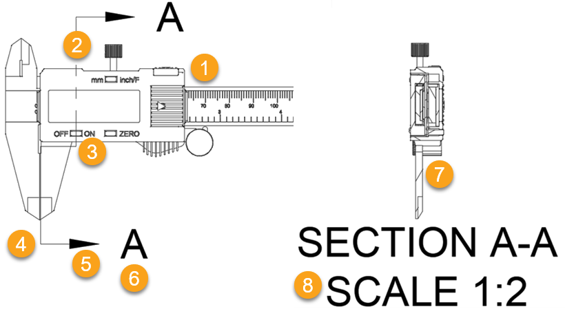
- Parent View: The drawing view from which the section view is generated.
- Section Line: Defines the line that cuts through the design.
- Bend Line: Defines a bend to shift where the section the cuts through a portion of the design.
- End Line: Defines the end of the section cut.
- Direction Arrow: Defines the direction in which the section view looks.
- Identifier: Defines the boundary that contains the detail and displays the identifier for the detail view.
- Section View: Displays the section cut through the design at the scale that you select.
- Section View Label: Displays the name, identifier, and scale for the section view.
Types of section views
There are 4 types of section views:
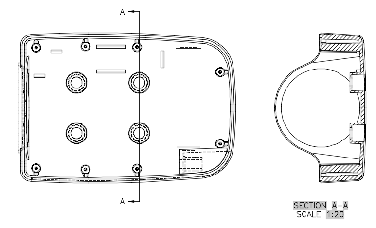
Full: Generated when the cutting plane passes through the entire drawing view.
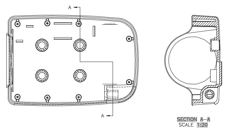
Half: Generated when the cutting plane passes through a portion of the drawing view.

Offset: Generated when the cutting plane bends to show features that do not fall along a straight section line.
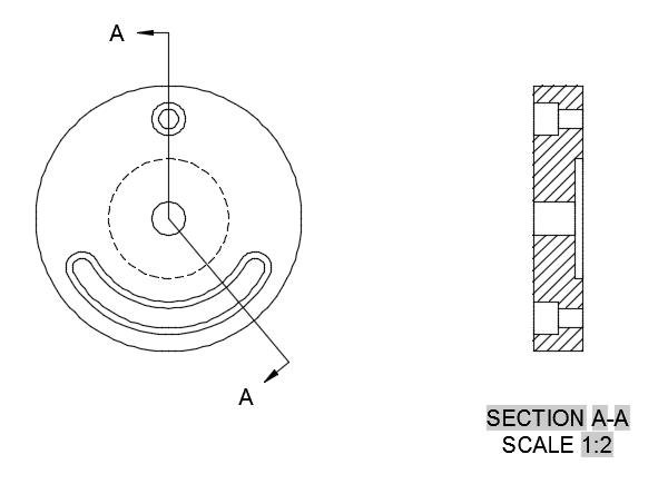
Aligned: Generated when the cutting plane passes through the entire drawing view along two non-parallel planes.
Associativity
If you move the parent view, the section line also moves.
If you adjust the section line, the section view automatically updates.
If you delete the section view, the section line and section view label are also deleted.
If you delete the section line, the section view and section view label are also deleted.
If you delete the section view label, the section view and section line both remain on the sheet.
Alignment constraint
When you place a section view, its location is constrained between the section view and the section line, so that the section view maintains linear alignment with the parent view. For most section views, the alignment constraint is horizontal or vertical alignment.
Shift key to toggle the alignment constraint off or on.ASME and ISO Standards
When you first create a drawing, the section view style is determined by the drafting standard (ASME or ISO) set in the Drawing workspace preferences.