Activity 1: Create a new drawing
In this activity, you:
- Save the model.
- Initiate a new drawing.
- Place a base view.
Prerequisites
- Fusion is started.
- Data file location: Samples > Basic Training > 08 - Drawings > Grinder_Vise.
A drawing view is an object that contains a 2D projection of a 3D model.
Steps
Save the Model.
With the Grinder_Vise design open, do the following:
If the model is "Read Only" (indicated in the title bar), click File > Save As.
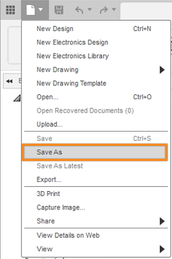
The Save as command is located under the File drop-down list.
Note: Even if a model is not "Read Only," you may wish to use the Save As command to preserve the original version of the model. Though a history of revisions is maintained, and you can revert to the original configuration, you might want to keep your changes confined to a new and separate version of the model.(Optional) Create a new Project to store your training models. Click + Project to do so, specify the project name, and press
Enter. After a short pause, the new project becomes the active project, and a blank file list appears on the right side of the Save dialog.(Optional) Create a new folder within the project to store your training models. Click + Folder to do so, specify a folder name, and press
Enter. Double-click the new folder to make it the current file saving location.Click Save.
Initiate a New Drawing.
With the Grinder_Vise design open, do the following:
Click on the Design icon on the left of the toolbar to view other available workspaces.
Move your cursor onto the Drawing workspace from the drop-down list.
Select From Design from the Drawing drop-down list.
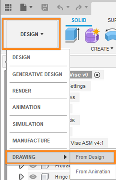
The From Design command is located under the Drawing drop-down list.
Choose the Assembly.
Select the Full Assembly option in the dialog (if it is not already selected).
Select ASME from the Drawing Format drop-down list.
Select in from the Units drop-down list.
Ensure that the B (17in x 11in) option is selected for the Sheet Size.
Click OK to initiate the drawing. Notice that a new file tab is automatically generated.
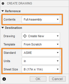
The Create drawing dialog.
Note: If you don't select Full Assembly in the New Drawing dialog, you can select individual or multiple components to create a drawing of part of the assembly.Tip: Hold Ctrl+click when selecting multiple components.You can set the drawing format, units, and sheet size before you create a drawing. However, you cannot change the drawing format or units after you create the new drawing.
Commit a Base View.
Move your cursor around the screen. Notice that the Base View preview is attached to the cursor.
Click on the bottom left quadrant of the sheet to place the view.
Click OK to commit the view.
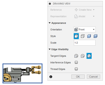 Note: After the view is committed, the shaded preview matures into a 2D line drawing of the view.
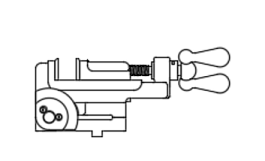
A 2D line drawing of the base view.
Activity 1 summary
In this activity, you:
- Saved the Grinder_Vise model to a personal folder.
- Initiated a new drawing.
- Placed a base view.