Activity 1: Define the PCB
In this activity, you start a PCB document from a schematic and define the basic size of the PCB board.
Steps
Switch to the PCB document.
From the schematic workspace, click Design > Switch > Switch to PCB document
 .
.Click Design > View > Zoom to fit
 .
.Confirm that you see the default PCB board with a yellow form and a black background, along with the components at the left-bottom of the board.
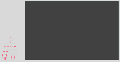
Default PCB with components.
Note: The components have white outlines. Green and red colors representing the leads for the components. Yellow lines representing how the leads are connected.
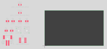
Resize the PCB.
Click and drag the right edge of the PCB until its width is slightly less than the height of the components.
Click and drag the top edge of the PCB until its height matches the height of the components.
Activity 1 summary
In this activity, you opened a PCB document from the Schematic workspace, and resized the PCB to an approximate size relative to the size of the components.