Activity 3: Routing wires on a PCB
In this activity, you route the wires for the circuits on the PCB. There are many ways in which the routes can be done. We will begin by showing how to manually route the PCB followed by using automatic tools. This activity is essential for understanding the different methods of routing and making the PCB design efficient and functional.
Creating routes manually in the PCB workspace.
Prerequisites
- Activity 2 is complete.
Steps
Optimize the location of the air wires.
Click Design > Polygon > Polygons Pour
 .
.This tool optimizes the route of the air wires (yellow lines).
Manually create routes.
Click Design > Route > Route Manual
 .
.Click one of the pins for LED1.
Drag the pointer and see how a red line shows where a route is created and how the air wire guides you to the pin at the end of the route.
Click the pin of the second component at the end of the yellow air wire.
Continue to create 3 or 4 other routes.
Note: You can change the layer between the top and bottom while making a route. When creating a route, press the space bar to get a Via. The via will appear attached to your pointer, click to place the via and continue routing on the bottom layer of the board.. The routes on the bottom side (layer) are blue.
Automatically route the signal wires.
Click Design > Unroute > Unroute All
 , to delete the routes you have created manually.
Click Design > Quick Route > Autorouter
 .
.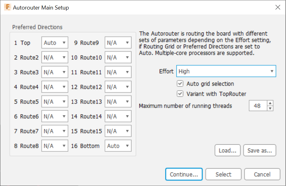 Note: The Top and Bottom layers are the layers used to route the board since the board is a 2 layer board.
Set the Effort to High. This uses more CPU but will be very fast for this design.
Click Continue.
Click Start on the Routing Variants dialog.
Use the arrow keys to scroll through the routing variants.
Pick a route that is optimized to 100%. Typically fewer Vias normally are best.
Select the route that you like best in the list and click End Job to place that route.
Activity 3 summary
In this activity, you routed the wires on the PCB. Initially, you started by manually routing your connections. Then you used an automated process that gave you several options and you picked the one you liked best.