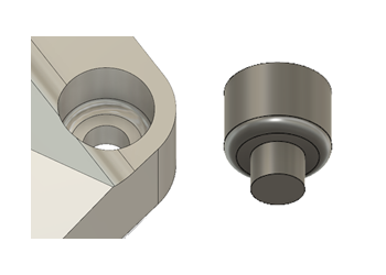
Create bolt hole obstacle geometry
Obstacle geometry is needed to prevent the generative solution from creating geometry in critical places.
For example, obstacle geometry may be needed to ensure that no geometry is placed inside holes designed for bolts. The Connector Obstacle ![]() tool can help create obstacle geometry for fasteners.
tool can help create obstacle geometry for fasteners.
The Connector Obstacle ![]() tool makes it easy for you to create obstacle geometry inside cylindrical holes, and uses a circular edge as the starting point. You can also use modeling tools to create the geometry, if you prefer. In this example, we will show you how to create obstacle geometry for the same bolt hole, first using the Connector Obstacle
tool makes it easy for you to create obstacle geometry inside cylindrical holes, and uses a circular edge as the starting point. You can also use modeling tools to create the geometry, if you prefer. In this example, we will show you how to create obstacle geometry for the same bolt hole, first using the Connector Obstacle ![]() tool, and then using other modeling tools.
tool, and then using other modeling tools.

- To access these modeling tools, in the Generative Design workspace, on the Define tab, click Edit Model > Edit Model
 .
. - When using the Connector Obstacle
 tool, build up the obstacle geometry one cylinder at a time.
 - Geometry created using the Connector Obstacle
 tool is automatically assigned as obstacle geometry. Geometry created using other modeling tools must be assigned a geometry type.
Using the Connector Obstacle tool
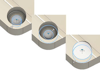
Start by selecting the bottom two circular edges. Then repeat with the two middle circular edges, and repeat again with the top two.

Once you have the three bodies, fillet the middle body to create the finishing obstacle geometry.
- In the Edit Model contextual environment, on the Edit Model Solid tab, click Create > Connector Obstacle
 .
. - Select the cylindrical edge at the bottom of the bolt hole.
- Confirm that the End of Shaft option is highlighted in the Connector Obstacle dialog, then click on the cylindrical edge that marks the top end of the narrow cylinder.
- Repeat the process, starting with the narrow cylindrical edge you ended on previously, and finishing with the cylindrical edge marking the start of the wide cylinder.
- Repeat the process again, starting with the cylindrical edge marking the bottom of the wide cylinder, and ending with the top cylindrical edge.
- Click on
 Body1 to hide it, so that only the obstacle geometry you just created is visible.
 - On the Edit Model Solid tab, click Modify > Press Pull
 .
. - Select the face of the middle body.
- Pull it outwards until it has the same diameter as the larger cylinder, then right-click and select OK.
- Click Press Pull
 again, then select the bottom edge of the middle cylinder.
 - Move the bottom edge upwards until it just meets the top edge, or until the fillet is as required, then click OK.
- On the Edit Model Solid tab, click Create > Extrude
 .
. - Select the top face of the largest body, and pull it upwards to ensure that no geometry is created in the space above the bolt hole.
- Click OK to close the Extrude dialog.
- The new geometry is automatically assigned as obstacle geometry.
Using the Fluid Volume tool
These instructions assume you have created preserve geometry to represent the bolt holes.
- Hide Body1 by clicking on its lightbulb
 , so that only the preserve geometry representing the bolt hole is visible.
 - On the Edit Model Surface tab, click Create > Patch
 .
. - Click on the top inside edge of the bolt hole preserve geometry, make sure the Operation in the Patch dialog is New Body, then right-click and select OK.
- Rotate the model and repeat the process with the bottom inside edge of the bolt hole preserve geometry.
- Band select the bolt hole preserve geometry.
- On the Edit Model Solid tab, click Create > Fluid Volume
 .
. - Select Internal for Volume in the Fluid Volume dialog, then click OK.
- On the Edit Model Solid tab, click Create > Extrude
 .
. - Select the top face of the new obstacle body, and pull it upwards to ensure that no geometry is created in the space above the bolt hole.
- Click OK to close the Extrude dialog.
- The new body must be assigned the geometry type Obstacle Geometry
 , in the Design Space panel of the Generative Design workspace.
Additional tips
| Quick Tip: Generative Connector Obstacles |