Create other obstacle geometry
Obstacle geometry prevents the generative solution from creating geometry where you don't want geometry created.
Create obstacle geometry using the modeling tools in the Generative Design workspace, then go to the Design Space panel to assign to it the geometry type, Obstacle Geometry.
In the Generative Design workspace, on the Define tab, click Edit Model > Edit Model ![]() to access these modeling tools.
to access these modeling tools.
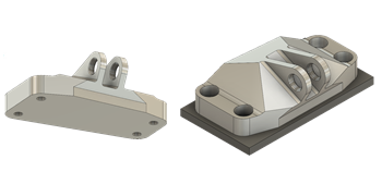
Keep new geometry above the bottom face of a model
If your model can be mounted on a surface, consider creating obstacle geometry to prevent the generative solution from creating geometry past the bottom face of the model.

- In the Generative Design workspace, on the Define tab, click Edit Model > Edit Model
 .
. - In the Edit Model contextual environment, on the Edit Model Solid tab, click Create > Box
 .
. - Rotate the model so the bottom surface is facing you.
- Select the bottom face of the model to select it as the modeling face.
- Draw a square that is just larger than the model. Adjust the dimensions in the Box dialog, if necessary.
- Change Operation to New Body, then click OK to close the dialog.
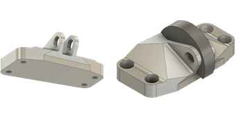
Maintain the range of motion
Create obstacle geometry to prevent unwanted geometry from being created by the generative solution, and thereby ensure your model can go through its range of motion. These instructions are specific for this model, to give you an idea of how to use the modeling tools. For more detailed instructions, see Create obstacle geometry to maintain the range of motion (tutorial 4).

- On the Edit Model Solid tab, click Create > Cylinder
 .
. - Select the inside face of the rear bracket as the starting point of the cylinder.
- To set the center of the cylinder, rotate the model so that the left view is facing you, identify the blue line that marks the bottom of the center channel, then move the cursor upwards towards the center of the channel, until the blue triangle appears that marks the center.
- Click on the blue triangle to mark the center of the cylinder, type a diameter that is large enough to block the center channel, then press Enter twice.
- Click on the blue arrow, select New Body as the Operation in the Cylinder dialog, then click on the inside face of the near bracket.
- Click OK to close the Cylinder dialog.
- On the Edit Model Solid tab, click Modify > Split > Split Body
 to remove the bottom half of the cylinder, which intersects with the model.
 - Click on the cylinder to select it, identify which body it is in the Browser, and click the Visible icon
 to hide it.
 - In the Split Body dialog, click Select associated with Splitting Tool, then click the bottom face of the bracket channel.
- Click OK to close the Split Body dialog.
- In the Browser, click the Visible icon
 that represent the two halves of the newly split cylinder.
 - Right-click on the body in the Browser that represents the bottom half that you want to eliminate, and select Remove to remove it from the Browser.