Structural loads in the Generative Design workspace
Loads enable you to simulate pushing, pulling, and twisting forces that your design should withstand.
Defining loads enables you to specify expectations towards a design strength. It is a critical part of the design requirements in a generative study and influences the final shapes of outcomes. You must apply at least one load to a preserve geometry body. A load and constraint can't be on the same face, edge, or vertex.
Defining loads
To define forces for a load case, use the Structural Loads ![]() command. You can access it from the Design Conditions panel of the Generative Design toolbar.
command. You can access it from the Design Conditions panel of the Generative Design toolbar.
You apply loads to the preserve geometry. It is displayed in green on the canvas.
A load direction is determined by a sign. If you enter a negative value, the load direction changes to the opposite.
Load types
You can apply the following loads:
| Load | Applied to | Used to |
|---|---|---|
| Faces, edges, or vertices | Apply a point load to simulate the action of this load on your model. | |
| Face (single or multiple) | Apply a pressure (force per unit area) to a defined area to simulate the action of this load on your model. Pressure is: - Uniformly distributed on a defined area. - Always applied normal to the selected faces. |
|
| Face (single or multiple) | Apply a load to simulate the action of torque on your model. | |
| Face (single or multiple) | Apply a load to simulate the action of cylindrical bodies pushing on one another, on your model. Note: The face must be cylindrical, and may be an outside face or an inside face (hole). It may be a full 360° cylindrical face or a partial one. |
|
| Face (single or multiple) | Apply a point load to simulate the effects of a force applied from a point in space that is not on your model. | |
| Face (single or multiple) | Apply a twisting load, from a remote location, to simulate the effect of torque on your model. |
Load case
The loads which act on a design depend on how it is used. Each considered use case is represented in a generative study by a load case.
The default load case is displayed in the browser. Double-click the load case to activate it. Next, define loads for the first considered use case there. If you need more load cases, you can clone or create them. Access the appropriate options from the context menu by right-clicking the load case in the browser.
The load case includes:
Gravity. It is a self-weight load. It is based on the properties of materials selected for a generative study.
Loads. They are the loads acting on a design in a given use case.
Constraint. Used to block movement in a given direction. Needed for each load case.
Loads in Generative Design - length: 05:51
Tips to avoid loads canceling each other out
If a load case includes loads of the same magnitudes and opposite directions applied to the same preserve geometry, they may cancel each other out.
As a result, these loads are not considered in the generation of outcomes.
| Example | Description |
|---|---|
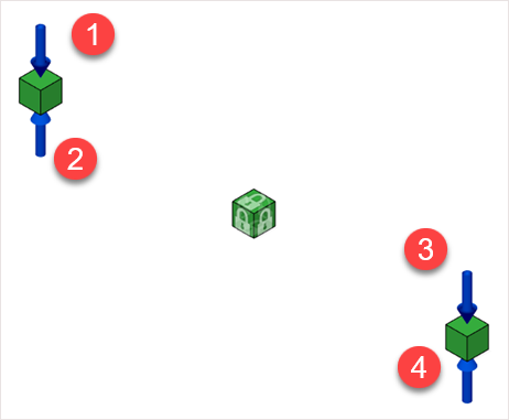 |
Example 1: Forces 1, 2, 3, and 4 are in one load case and have equal magnitudes. The resultant magnitude equals zero. The geometry is not loaded. As a result, the loads are not considered in the generation of outcomes. |
 |
Example 2: Forces 1, 3 are in load case 1 and forces 2 and 4 in load case 2. All forces have equal magnitudes. The load definition is correct. These loads are in different load cases, so the resultant magnitude is different from zero. |
Load magnitudes
Magnitudes of loads acting on the design depend on the design mass and how it is used in a given use case.
For some designs, you need to consult experts to estimate accurately the magnitudes.
The accurate representation of the requirements enables you to fully explore the design space for options. Overestimating the magnitudes may result in outcomes that use too much material, or use stronger material than required. It may impact manufacturing costs. If you underestimate the load magnitudes, it may lead to outcomes of insufficient strength.
For many designs, referring to real-life examples may be helpful.
Structural load types
For more information about the types and definition of structural loads available in the Simulation workspace, see structural loads.