2.5-axis milling parameters
| Parameter | Details |
|---|---|
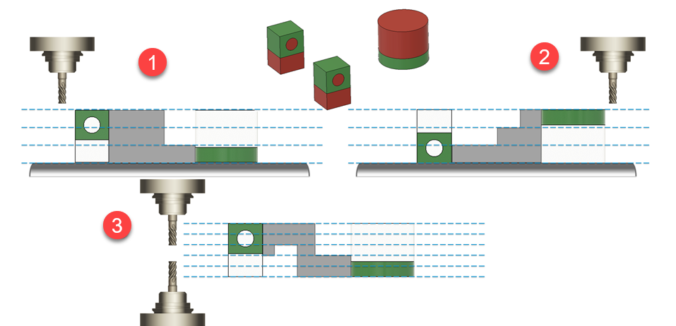
| Tool Direction | Orients the tool in the direction parallel to the X, Y, or Z axis of the triad. For example if you select the Z button, then the tool is oriented parallel to the Z axis of the triad. As a result of generation, you receive three outcomes considering three layering variants: Z+, Z-, and +/-Z. You can select only one direction. Click X, Y, or Z button to set the attack tool direction. |
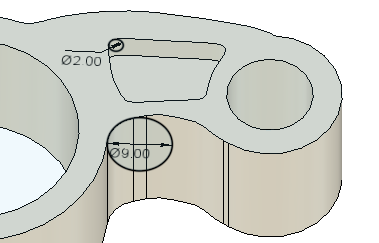
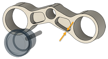
| Minimum Tool Diameter | Specifies the diameter of the smallest cutting tool that you plan to use in the milling operation. Sometimes, the specified tool may become so long that it makes machining difficult. Then, corner radiuses may be generated larger than the specified minimum tool diameter. For example, the pocket in the part below is shallow enough to be cut with the specified 2-mm tool. However, the exterior profile of this part is generated with a larger radius to accommodate a longer and larger-diameter end mill.  A tool diameter is increased above the Minimum Tool Diameter value so that the distance from the top of the part to the bottom of each pocket or profile is at least twice the tool diameter. |
| Minimum Wall Thickness | Attempts to enforce the minimum thickness of a wall or rib after milling, considered in the setup of a generative study. Tip: To support enforcing this parameter:
 |
Example - three 2.5-axis outcomes depending on the milling setup

Outcome 1: three layers, one setup
Outcome 2: three layers, opposite setup
Outcome 3: five layers, two setups.