Activity 2: Modify the height, angles, supports, and size of a doorstop
In this activity, you
- Open the doorstop design from the Basic Training > 04 – Modeling folder
- Extrude the model to give it height
- Create angles along the top, sides, and front to make it more functional
- Make the model bigger
Steps
Open the Door_Stop design in Basic Training > 04 - Modeling.
In the Samples section of your Data Panel, browse to Basic Training > 04 - Modeling.
Double-click the thumbnail image or model name to open the Door_Stop model.
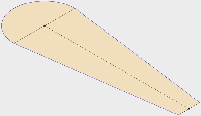
Extrude the Door_Stop sketch to create two separate 50mm bodies.
Click Extrude
 on the toolbar under Solid.
Select the semicircular sketch.
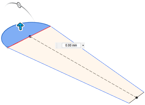
In the Distance box that opens, enter 50 mm.
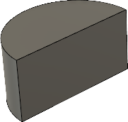
When the body is extruded, the other body in the sketch becomes hidden.
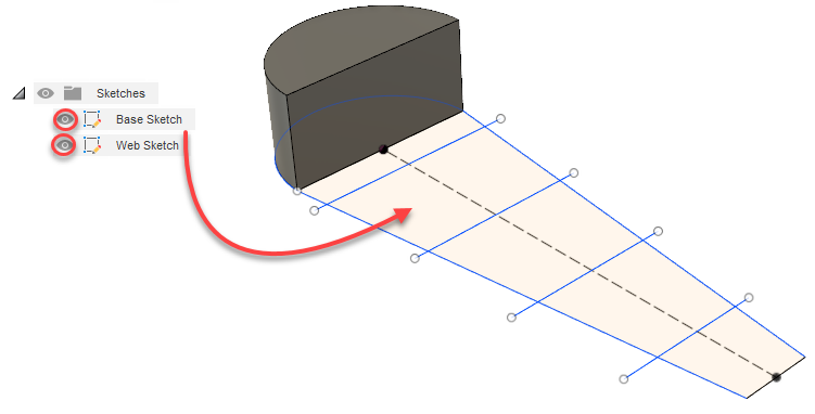
To show the other body again, expand the Sketches node in the browser and turn on visibility
 for the Base and Web sketches.
On the toolbar, under Solid, click Extrude
 again.
Select the longer portion of the of the sketch.
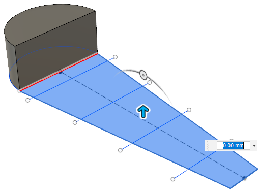
In the Extrude dialog that opens, set the Distance to 50 mm and the Operation type to New Body.
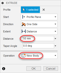 Tip: If you don’t set the operation as New Body, by default Fusion will join the two extruded bodies together.
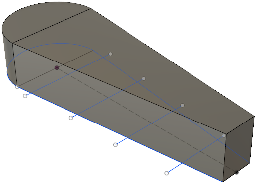
Angle the top of the doorstop downward with a 10-degree angle.
Click the top left-front corner of the ViewCube to rotate the model.
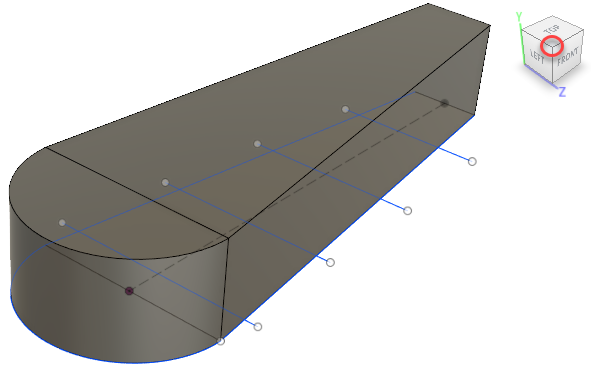
Expand the Bodies node and turn off visibility
 for Body5.
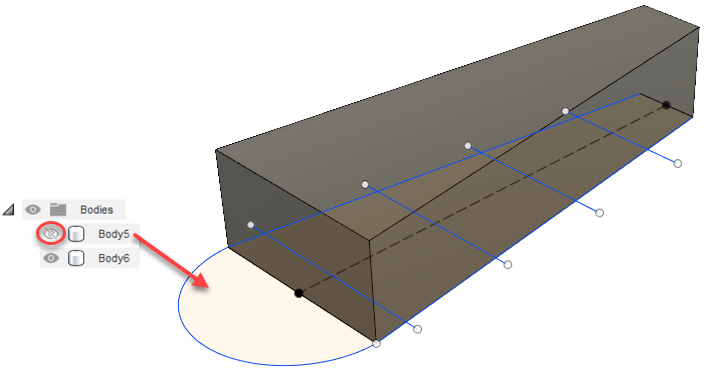
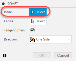
On the toolbar, click Modify > Draft.
The Draft dialog displays, with Plane set to Select.
Click the larger of the two vertical end-planes (the one closest to you).
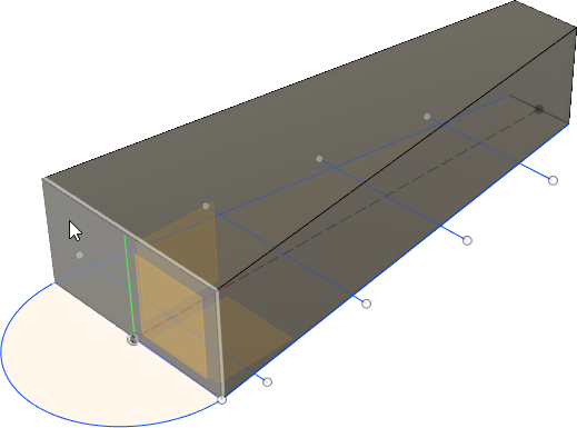
This is now the assigned plane for the Draft function, and Faces is now set to Select in the Draft dialog.
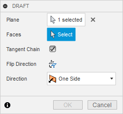
Click the top face in the sketch.
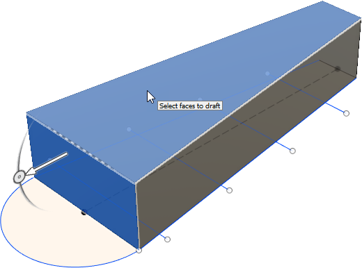
This is the face that you will draft.
Click and drag the arrowhead to point it in the opposite direction (inward to the model).
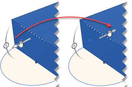
In the Draft dialog, enter 10 deg as the angle and click OK.
The draft is applied and the top face angles downward.
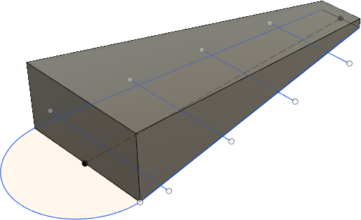
Angle the outer faces by 15 degrees.
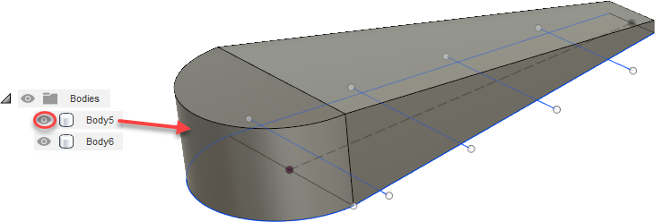
Under the Bodies node in the browser, set Body5 to visible
 .
.
Click the bottom left-front corner of the ViewCube to show the bottom of the model.
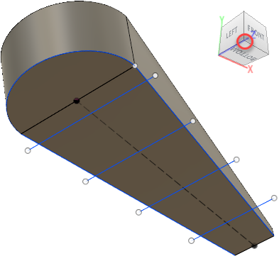
On the toolbar, select Modify > Draft.
The Draft dialog displays, with Plane set to Select.

Click the large bottom plane of the model.
This is now the assigned plane for the Draft function, and Faces is set to Select in the Draft dialog.

Hold
Ctrl(Windows) orCommand(MacOS) and, while moving around the model with the ViewCube, select the two long sides and the round face.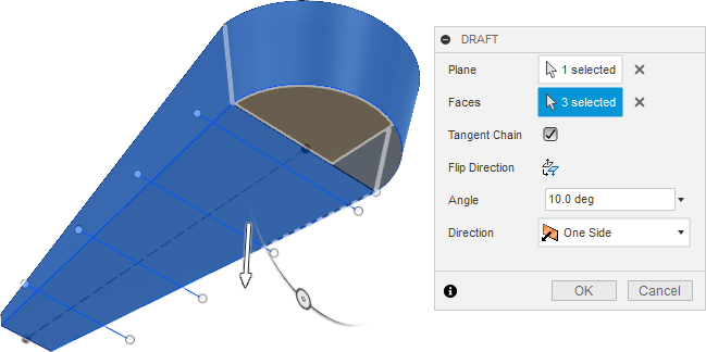
These are the faces that you will draft.
Enter 15 deg in the Angle box to apply angles to the selected faces.
The sides and back are now angled more like a doorstop.
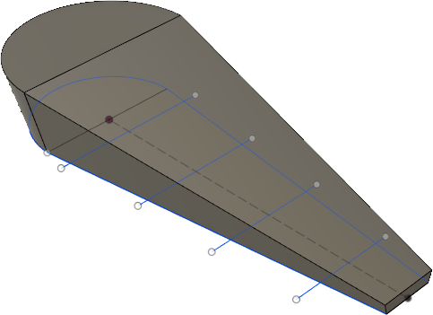
Apply a chamfer to the front end of the doorstop to create a 35-degree angle with a distance of 10mm, so that the doorstop will fit better under a door.
Click Modify > Chamfer on the toolbar.
The Chamfer dialog displays with Edges set to Select.
Select the top edge of the short end of the doorstop.
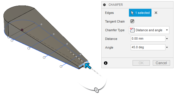
In the Chamfer dialog, set Chamfer Type to Distance and Angle, enter 10 mm in the Distance box, and set the Angle to 35 deg.
The chamfer is applied and the front end of the doorstop is now angled.
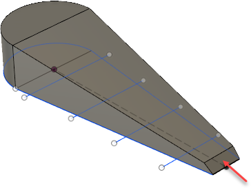
Combine the bodies so you can do other tasks with the model, such as 3D printing.
Click Modify > Combine on the toolbar.
The Combine dialog displays with Target Body enabled. The target body is the body that other bodies will be joined to, and which will remain as a node in the browser.
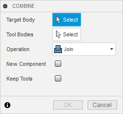
Expand the Bodies node in the browser.

In the browser, click Body5 (as target body), click Body6 (as tool body), and make sure Operation is set to Join.
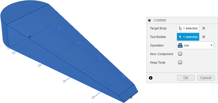
Click OK.
The two bodies are combined into Body5, which is now the only body node in the browser.
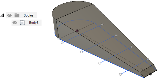
Make a 5mm thick shell out of the body.
Expand the Sketches node and turn off visibility
 for the Base Sketch.
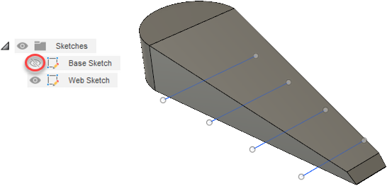
Use the ViewCube to show the bottom of the model.
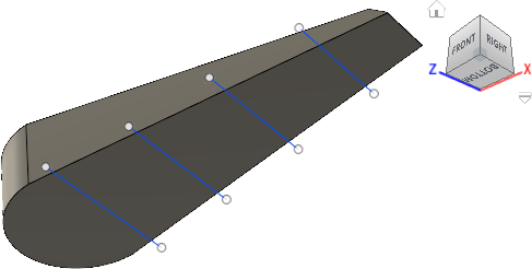
Select Modify > Shell on the toolbar.
The Shell dialog displays with Faces/Body set to Select.
Click the bottom face of the model to select it as the face that will be removed to create the shell.
Enter an Inside Thickness of 5 mm in the Shell dialog.
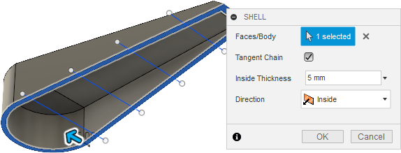
The shell is created and the doorstop is now hollow.
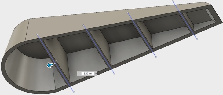
Create 5mm supports inside the doorstop to strengthen it.
Expand the Sketches node in the browser and make sure that Web Sketch is visible
 .
.
Click Create > Web on the toolbar.
With the Web dialog open and while holding down Ctrl (or Command for Mac), select the four support lines that cross the doorstop.
Set Thickness Options to Symmetric, Depth Options to To Next, and Thickness to 5 mm.
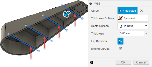
If you see an error message about sweep inputs, click Flip Direction in the Web dialog.
Click OK.
The supports are created inside the doorstop.
Expand (scale) the model by 5% (a factor of 1.05).
Return to the ViewCube home view.
Expand the Sketches node in the browser and set the visibility
 of Base Sketch to on and Web Sketch to off.
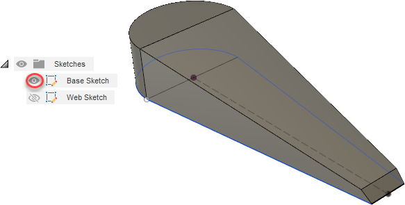
Select Modify > Scale on the toolbar.
The Scale dialog displays with Entities set to Select.
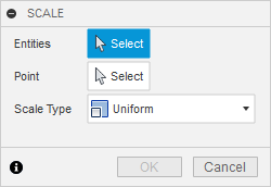
For the Point option, click Select. Then click the point in the middle of the model.
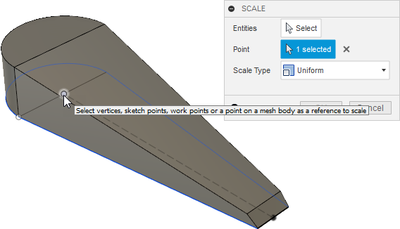
Set Entities to Select and click anywhere on the model to select it as an entity.
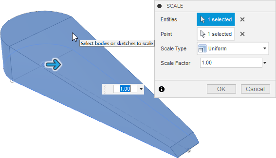
Enter 1.05 in the Scale Factor box and click OK.
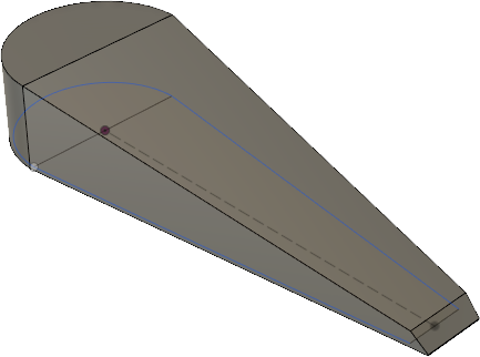
The model is enlarged by 5%.
Activity 2 summary
In this activity, you
- Opened the doorstop design from the Basic Training > 04 – Modeling folder
- Extruded the model to give it height
- Created angles along the top, sides, and front to make it more functional
- Made the model bigger