Activity 1: Edit features using parametric modeling
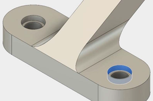
In this activity, you increase both the size of the counterbore holes in the foot of the brace, and the thickness of the web.
Prerequisites
- Fusion is started.
- Data file location: Samples > Basic Training > 04-Modleing > Bearing_Bracket.f3d
Steps
Open the starting model, Bearing_Bracket, from the Basic Training folder in the Data Panel
If the Data Panel is not currently shown, click Show Data Panel
 at the top of the screen.
The top level (home view) of the Data Panel is divided into two subsections: ALL PROJECTS and SAMPLES. Scroll down until you reach SAMPLES.
Double-click the Basic Training folder to open it.
Double-click the 04 - Modeling folder to open it.
Double-click the Bearing_Bracket model to open it in the canvas.
Note: When you open a sample design in Fusion for the first time, it appears in the Model workspace.
Identify a personal project in which to save the starting shape models. Sample models are read-only and must be saved to a personal project.
- Click File > Save as
 .
. - Enter a name, such as Bearing Bracket, in the name field.
- Expand the arrow button next to the Location field.
- Locate and click on an existing project, or click New Project to start a new project.
- Click File > Save as
Identify or create a folder in which to save the starting shape models.
- Double-click on a folder in the project to select it, or create a new folder.
- To create a new folder, click New Folder.
- Type a name, such as Bearing Bracket for the folder.
- Press Enter.
- Double-click the folder to make it the current file saving location
- Click Save
Increase the size of the counterbore holes in the foot of the brace. Set the diameter to 20 millimeters, the counterbore depth to 7.5 millimeters, and the counterbore diameter to 27.5 millimeters.
Right click on the inside face of one of the holes in the canvas, and select Edit Feature.
In the Edit Feature dialog, set the
diameter to 20 millimeters
counterbore depth to 7.5 millimeters
counterbore diameter to 27.5 millimeters
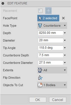
Click OK to finish tool and close the Edit Feature dialog.
Increase the thickness of the web to 7.5 millimeters.
Double click on the web feature
 in the timeline.
In the Edit Feature dialog, increase the thickness to 7.5 millimeters.
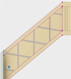
Click OK to finish the tool.
Activity 1 summary
In this activity, you increased both the size of the counterbore holes in the foot of the brace, and the thickness of the web.
You accomplished this task using the following tools:
- Edit Feature