Activity 2: Edit features using direct modeling
In this activity, you switch to direct modeling mode to alter the angle of bearing arm, and then you restart the design history.
Prerequisites
- Activity 1 is complete.
Steps
Change to direct modeling.
Click the gear icon in the bottom right corner of the window.
Click Do not capture Design History
 .
.In the Warning dialog, click Continue to delete the timeline and switch to direct modeling.
Note: The timeline disappears from the bottom of the canvas, and all the modeling items are captured in the Browser.
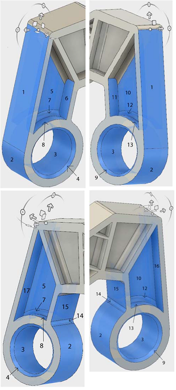
Select the 17 faces of the arm, as the objects to move.
Click Design > Solid > Modify > Move/Copy
 .
.In the Move/Copy dialog, set the Move Object to Faces.
Click on the 17 faces of the arm, to select them as the Move Objects.
Note: Confirm that 17 objects are selected in the Move/Copy dialog.
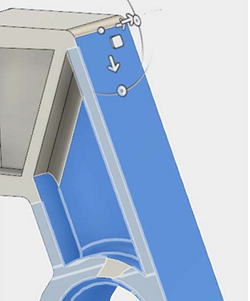
Move the pivot point to the center of the upper edge of the top, long exterior face of the arm.
In the Move/Copy dialog, click Set Pivot
 .
.Click the center of the upper edge of the top, long exterior face of the arm.

In the Move/Copy dialog, click Set Pivot
 .
.
Move the bearing arm upwards 30 degrees about the x-axis.
- In the Move/Copy dialog, change the X Angle to -30 deg.
- Click OK to finish the tool and close the Move/Copy dialog.
Re-enable the Design History, to switch back to parametric modeling.
In the Browser, right-click on the Bearing_Bracket component
 .
.Click Capture Design History
 .Note: The timeline has restarted, with a single base feature.
Activity 2 summary
In this activity, you switched to direct modeling mode to alter the angle of bearing arm, and then you restarted the design history.
You accomplished this task using the following tools:
- Move/Copy