Loft reference
The Loft tool creates a smooth solid body that transitions between two or more sketch profiles or planar faces in Fusion.
Design > Solid > Create > Loft ![]()
The Loft dialog displays options for the currently selected profile. Select the profile label in the graphics window to modify options for that profile.
Feature tab
Select geometry and define the loft settings.
Profiles
Select the sketch, edge, or face for the profile.
![]() Reorder Click to change the order of the profiles in the Loft.
Reorder Click to change the order of the profiles in the Loft.
End condition Controls the transition away from the start and end profiles of the Loft. The end conditions available depends on the type of geometry selected for the profile.
 Free No end condition applied.
 Direction Applies an angle measured off the sketch plane. Available when the Loft profile is a 2D sketch.
 Tangent Applies a G1 condition off the Loft profile. Available when the Loft profile is the edge or face of a body.
 Smooth Applies a G2 condition off the Loft profile. Available when the Loft profile is the edge or face of a body.
 Sharp Transitions to a sharp point. Available when the profile is a sketch point or construction point.
 Point Tangent Applies tangency at the point to create a dome shape transition. Available when the profile is a sketch point or construction point.
![]() Add Adds a row to the profile table.
Add Adds a row to the profile table.
![]() Remove Removes the selected profile row.
Remove Removes the selected profile row.
Guide Type
 Rail Rails are 2D curves or 3D curves that affect the Loft shape between sections. You can add any number of rails to refine the shape of a loft. Rails must intersect each section, and must terminate on or beyond the first and last sections. Rails must be tangent continuous.
 Centerline A centerline is a type of rail to which the Loft sections are held normal, which causes behavior like a sweep path. Centerline lofts maintain a more consistent transition between the cross-sectional areas of selected Loft sections. Center lines follow the same criteria as rails, except they need not intersect the sections, and only one can be selected.
Rails/Guide
![]() Add Adds a row the table.
Add Adds a row the table.
![]() Remove Removes the selected row from the table.
Remove Removes the selected row from the table.
Chain Selection
- Chain Selection ON: Adjacent edges are selected together and included as one profile.
- Chain Selection OFF: Adjacent edges are selected individually.
Closed
Check to connect the first and last profiles to each other and create a closed loop Loft.
 |
 |
| not closed | closed |
Takeoff Weight
Available when the end condition is set to Direction. Specifies the amount of influence the takeoff angle has along the Loft path.
Takeoff Angle
Available when the end condition is set to Direction. Specifies the start angle of the transition from the profile.
Tangency Weight
Available when the end condition is Tangent, Smooth, or Point Tangent.
Tangent Edges
Specifies whether the Loft operation merges tangent edges or not.
- Merge Merges tangent edges.
- Keep Keeps the tangent edges unmerged.
Operation
Select an operation to control how the feature affects the design.
 Join: Combines the new body with an existing body.
 Cut: Cuts an area out of an existing body.
 Intersect: Creates a body at the intersection of an existing body and the new body.
 New Body: Creates a new body in the active component.
 New Component Creates a new body in a new component. (Hybrid Design type only)
Objects To Cut
Select to recompute bodies or maintain the current bodies.
- Auto-Select re-computes the bodies to cut based on the current visibility state.
- # Bodies cuts the same bodies that were included when the cut operation was created.
Available for cut operations only. The option is only active when you edit operations.
When you create a cut operation, the bodies to affect are determined based on visibility. Bodies that are visible will participate. Bodies that are not visible will not participate.
When you edit the operation in the timeline, the cut is recalculated. You can choose to recompute the bodies to cut (Auto-select) or keep the bodies that were used when the operation was created (# Bodies).
Analysis tab
Lets you analyze the quality of surface curvature on the previewed result in the canvas.
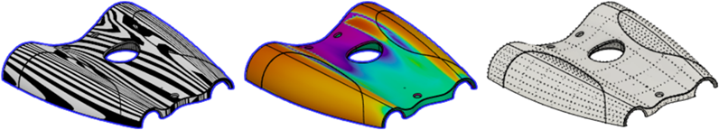
Analysis Type
Select an analysis type to visualize the quality of surface curvature on the selected body.
| Type | Description |
|---|---|
| None | Displays no analysis. |
| Zebra | Displays alternating black and white stripes on a body to help you analyze surface curvature. |
| Curvature Map | Displays a color gradient on a body to help you analyze areas of high and low surface curvature. |
| Isocurve | Applies UV mapping and curvature combs to help you analyze the quality of the surface curvature. |
Bodies
Select bodies to analyze.