Create a perpendicular plane
Use Perpendicular Plane in the Construction Geometry dialog to create a construction plane perpendicular to a selected face or construction plane in Fusion.
On planar faces and construction planes, set Plane Direction (U or V), Distance, and optional Reference Object inputs to control orientation and placement. On curved faces (cylindrical, conical, or toroidal), pick a location on the face; the plane orients to the surface normal at that point. Select an Extent Type option to size the plane.
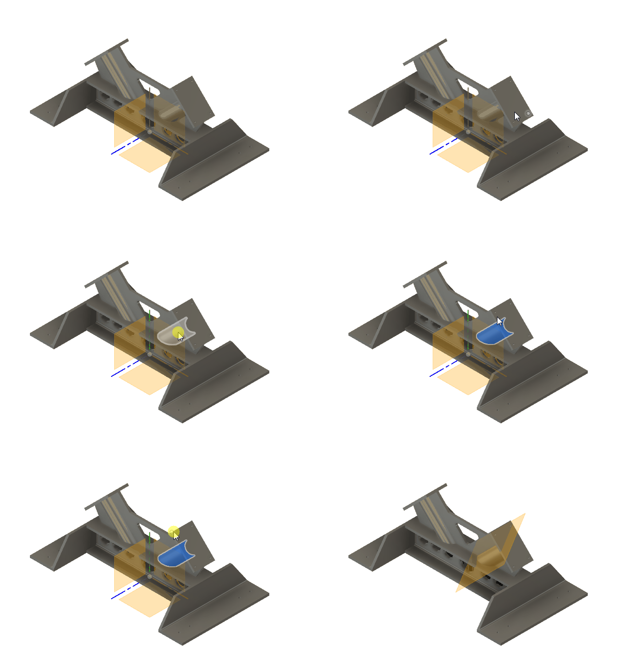
On the toolbar, select Construct > Perpendicular Plane
 .
.The Construction Geometry dialog displays, Type is set to Plane and Method is set to Perpendicular Plane.
In the canvas, select a face or construction plane.
- For a planar face or construction plane, set Plane Direction to U or V to choose which in-plane direction drives the perpendicular orientation.
- For a curved face (cylindrical, conical, or toroidal), pick a location on the face. The plane orients to the surface normal at that location.
Optional: Select a Reference Object to position the plane.
When the input face is curved, select a vertex, construction point, or sketch point.
When the input face is planar, select a vertex, construction point, sketch point, planar face, or construction plane.
If you skip a reference object, placement uses the location you pick on the face or plane.
Enter Distance or drag the manipulator to offset the plane along the perpendicular direction.
Select an Extent Type option to size the plane:
- Distance: Specify the plane size.
- To Object: Extend the plane to a sketch profile, sketch, or other object you select.
Optional: Set Resize:
- Default: Size the plane to fit the selected geometry.
- Extended: Size the plane to fill the current view.
Click OK.
The new construction plane appears in the canvas, perpendicular to the reference you selected. To change inputs later, edit the feature from the timeline or browser.
Tips
- Create construction planes when you want sketches that do not lie on one of the three default planes.
- Use construction planes as inputs for other tools, such as the cutting tool in Split Body.
- Plane Direction and Distance often replace extra reference geometry when you only need a perpendicular plane in a specific orientation and location.
- On curved faces, pick the location first, then use a point Reference Object if you need the plane anchored to specific geometry.
- Reference Object rules depend on the input face: curved faces accept point references only; planar faces accept points or planar face / construction plane references.
- Resize controls how large the plane displays in the canvas. Extent Type controls the plane's geometric dimensions.
- To show or hide plane name labels on the canvas, see Show or hide plane names on the canvas.