Minimum Radius Analysis reference
Minimum Radius Analysis shows areas of a model that are at or below the minimum radius. Displays colors on the model that represent the minimum radius for the curvature of concave faces. Detects the minimum fit for holes and fillets. Useful for determining tool sizes in manufacturing projects to see what areas will be missed with a certain cutter radius.
Design or Manufacture > Inspect > Minimum Radius Analysis ![]()
In the example above, inside fillets that are less than 1.6MM are shaded in green. Inside fillets that are greater than 6MM are shaded in red.
- Select Inspect > Minimum Radius Analysis.
- Select the body or multiple bodies you want to analyze.
- Set the Maximum Tool Radius.
- Set the Minimum Radius.
- Use the slider to see the variations between the Max/Min values.
- Set the opacity.
- Click OK.
In the example above, Minimum Radius Analysis highlights the areas of concave curvature. For tool radius of 0, these are all green, but as you increase the tool radius, you can see that some parts are shaded in red, as these have too high curvature to be correctly manufactured by the tool of that radius.
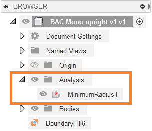
You can control the visibility of this new analysis. In the Browser, expand the Analysis folder, and click the light bulb in from of the analysis you want to view or hide. You can also edit the analysis by right-clicking it and selecting Edit.