Activity: Measure the part
In this activity, you make several measurements to ensure the components of the Geneva drive will rotate without binding by having clearances between components.
Steps
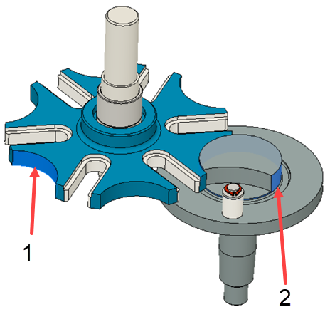
Use the Measure tool to compare the radii of the mating radii on the cross and rotor components.

Selection locations: 1- on the cross, 2- on the rotor.
In the Design workspace, click Inspect panel > Measure.
Select the large radius face on the cross component labeled as 1 in the figure.
Note the radius of the feature.
- Click Restart Selection on the Measure dialog.
- Select the incomplete radii on the rotor component labeled as 2 in the figure.
- Note the radius of the feature.
The radius on the cross is slightly larger than the radius on the rotor, therefore the parts will fit together well, relative to the radii.
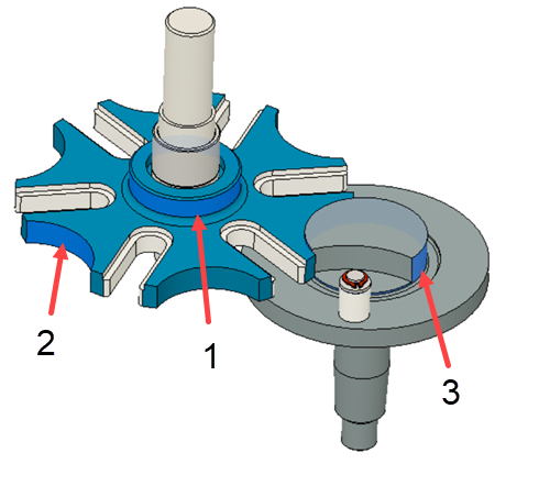
Use the Measure tool to verify that the cross component and rotor component are properly positioned relative to each other.

In the Design workspace, click Inspect panel > Measure.
Select the large diameter in the center of the cross component labeled as 1 in the figure.
Select the radius of the cross component labeled as 2 in the figure.
Note the Distance and Minimum Distance. The Distance is the length between the centers of the two radial features.
Click Restart Selection on the Measure dialog.
Select the large diameter in the center of the cross component labeled as 1 in the figure.
Select the incomplete radii on the rotor component labeled as 3 in the figure.
Note the Distance and Minimum Distance.
The Distance of the two measurements made are the same, but the Minimum Distances are different, with the measurement for the rotor is smaller. This smaller distance results in a gap between the cross and rotor components, and the gap is due to the different in the radius that you measured first.
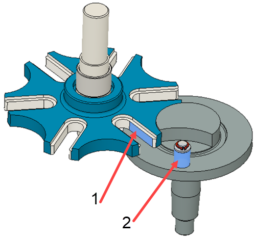
Measure the diameter of the Rotor’s pin to ensure it fits in the slots of the cross components.

In the Design workspace, click Inspect panel > Measure.
Select the face of the slot labeled as 1 in the figure.
Select the parallel face of the slot to find the distance.
Note the Distance represents the width of the slot. The diameter of the pin must be less than this dimension.
Click Restart Selection on the Measure dialog.
Select the diameter of the pin labeled as 2 in the figure.
Note the diameter of the pin.
The diameter of the pin is smaller than the width of the slot, so the rotor will not bind in the slots of the cross.