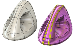
Bevel edges of a T-Spline body
Learn how to use the Bevel Edge tool to modify the sharpness of a T-Spline body by offsetting T-Spline edges in Fusion.

In the Design workspace, in the Form contextual environment, click Modify > Bevel Edge
 .
.The Bevel Edge dialog displays.
In the canvas, select one or more T-Spline edges to bevel.
In the dialog, specify the a Distance Mode and then specify its associated settings to position the new edges:
- Bevel Width: Lets you specify a distance to determine the bevel width to create a bevel with sides of equal distance.
- Width: Specify the distance between the outer edges of the bevel.
- Relative Offset: Lets you specify a distance to determine the bevel width to create a bevel with sides of equal distance.
- Offset Ratio: Specify a ratio value between 0 and 1 to determine the offset of the outer edges relative to the original edge.
- Bevel Width: Lets you specify a distance to determine the bevel width to create a bevel with sides of equal distance.
Specify the number of Segments to insert additional faces between the offset edges.
(Optional) Specify a Spacing type:
- Uniform: Spaces segments are spaced equally across the bevel.
- Parametric: Spaces segments parametrically along the bevel so the inner segments are narrower than the outer segments.
(Optional) Specify a Crown value to flatten or round the bevel surface:
- Enter '0' to create a flat bevel.
- Enter a value between '0' and '2' to create a rounded profile. A value less than 1.0 creates a flatter profile and values higher than 1.0 creates a more convex profile.
Click OK.
The selected edges are sharpened or softened on the T-Spline body and displays in the canvas.
Tips
- Double-click a T-Spline edge select the full loop of edges.
- The smaller the Bevel Location number, the closer together the new edges will be, resulting in a sharper surface.
- Bevel Edge adds more control along an edge which allows more control of the body.
- The flow of the edge direction can be influenced using Bevel Edge to insert edges from two directions on a body.
- Once the target edge is selected, drag the manipulator to set the desired distance of the bevel location. Change the segment count to add more edges.