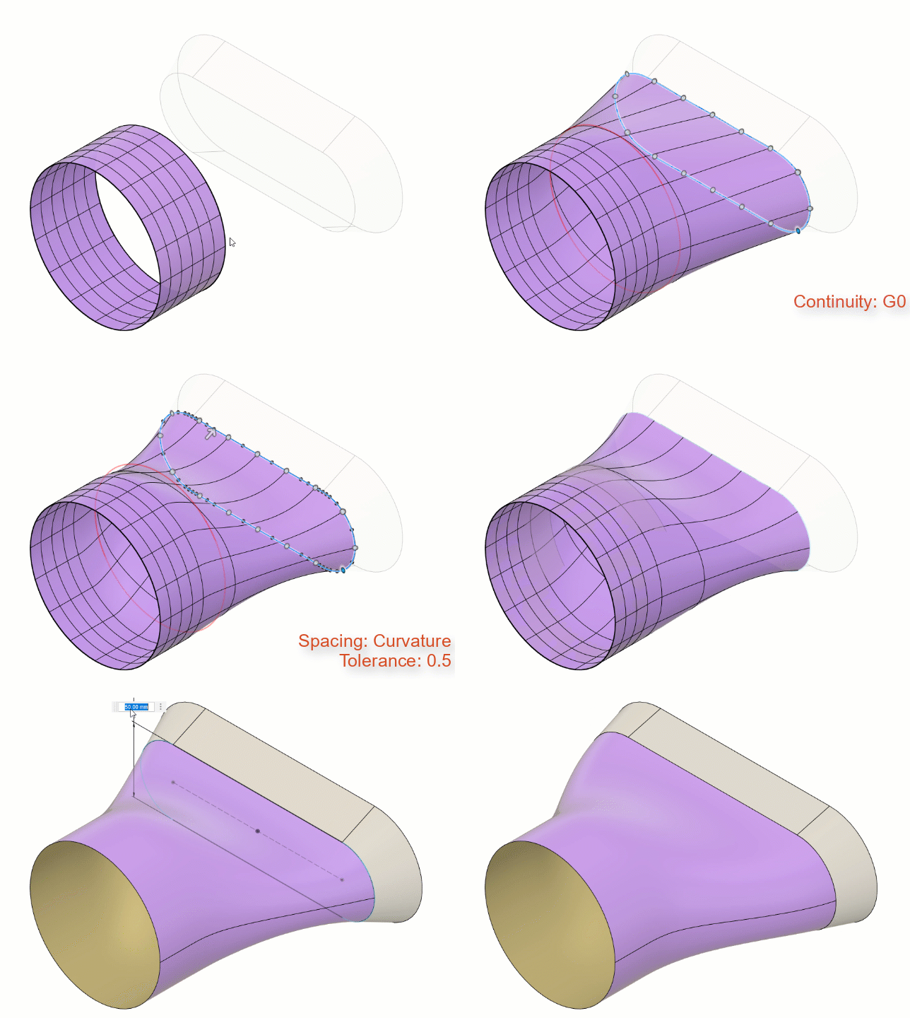
Match T-Spline edges to solid, surface, or sketch geometry
Learn how to use the Match tool to align the edges of a T-Spline body with sketch curves or edges on a solid or surface body in Fusion.

In the Design workspace, Form contextual environment, select Modify > Match
 .
.In the dialog, check Associative to create an associative relationship between the T-Spline geometry and the parametric solid, surface, or sketch geometry.
In the canvas, select a set of T-Spline Edges to form the first side of the match.
Select sketch curves or edges on a solid or surface body as Match Edges to form the other side of the match.
A preview of the match geometry displays in the canvas, spanning between the T-Spline Edges and the Match Edges.
Optional: Adjust the Continuity across the match transition to faces on a solid or surface body:
- Connected (G0): Applies G0 positional continuity.
- Tangent (G1): Applies G1 tangent continuity.
- Curvature (G2): Applies G2 curvature continuity.
Optional: Adjust the Spacing to control the distribution of control points along the match edge:
- Uniform: Distributes control points evenly.
- Curvature: Distributes control points based on the curvature of the match edge.
Click OK.
The adjusted edges display on the T-Spline body in the canvas.
If the match is Associative, when you modify the solid, surface, or sketch geometry in the parametric design environment, the T-Spline edges adjust to maintain their relationship with the match edges.
Tips
- Check Associative to create an associative relationship between the T-Spline geometry and the parametric solid, surface, or sketch geometry.
- If the geometry between the T-Spline Edges and Match Edges intersects itself, click Alternate Alignment to switch the direction of the control points around the match edge, clockwise or counterclockwise.
- Use the Tolerance settings to control the deviation of the T-Spline edge from the match edge.
- Use the Falloff settings to control how much of the T-Spline is influenced by the match.
- Drag the control points along the match edge to fine-tune the alignment.