Activity 1: Create a sheet metal flange from a sketch profile
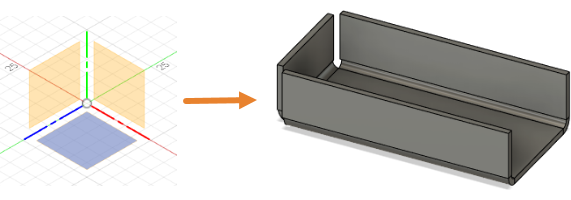
In this activity, you create a simple sheet metal flange. To accomplish this you
Confirm your document settings are set to mm
Create a closed sketch profile using the 2-Point Rectangle tool
Create a base flange from the sketch profile
Add features to the base flange to create the sheet metal flange.
Prerequisites
- Fusion is started.
Steps
Confirm that your document settings are set to mm.
- In the Browser expand
 Document Settings.
 - Confirm the
 Units are set to mm.
 - If you need to change the units, hover over Units and click
 Change Active Units
 - In the Change Active Units dialog, change the Unit Type to Millimeter.
- Click OK to accept the tool and close the dialog.
- In the Browser expand
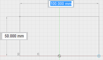
Using the tools in the Sheet Metal tab, create a closed rectangular sketch profile, measuring 100 mm x 50 mm.
- Click
 (Design workspace > Sheet Metal tab > Create panel > Create Sketch) to initiate a sketch.
 - Select a sketch plane, to open the Sketch Palette.
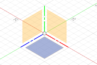
- Click
 (Design workspace > Sheet Metal tab > Create panel > 2-Point Rectangle) to activate the 2-Point Rectangle tool.
 - Click on the canvas to place the first point of the rectangle and drag the cursor to create a rectangle that measures 100 mm x 50 mm.Tip: Consider enabling Snap to Grid to make sizing easier.
- Press Enter on your keyboard, to complete the tool.
- In the Sketch Palette dialog, click Finish Sketch.
- Click
Create the base Flange, as a New Component, based on the sketch profile and using the default Sheet Metal Rule. Let's skip applying the sheet metal rule for now; we will get to that later.
- Click
 (Design workspace > Sheet Metal tab > Create panel > Flange) to open the Flange dialog.
 - In the canvas, select the sketch profile.
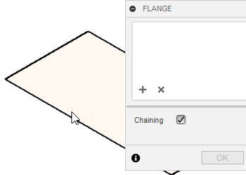
- In the Flange dialog, set the Operation to
 New Component
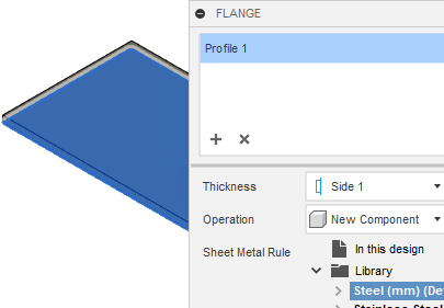
- Click OK to apply the tool and close the dialog.Note: The sheet metal component is labelled in the Browser by the
 icon.
icon.
- Click
Create the sheet metal flange from the two long edges and one short edge of the base flange. Set the height to 25 mm, and accept the default settings for the rest of the dialog options: Bend Position set to Inside, and the Angle set to 90 degrees.
- Click
 (Design workspace > Sheet Metal tab > Create panel > Flange) to open the Flange dialog.
 - In the canvas select the two long edges and one short edge, where the flanges will be created.Note: You may want to zoom in and confirm that you have selected the inside edge in all three cases.
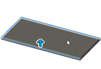
- In the grip, type 25 to specify the height, or if the grip is not visible, set the Height to 25 mm in the Flange dialog.Note: Flanges created from co-planar edges automatically miter at corners that would otherwise interfere. You can change the Miter Option in this dialog.
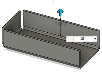
- Click OK to apply the tool and close the Flange dialog.
- Click
Activity 1 summary
In this activity, you created a simple sheet metal flange. To accomplish this you
- Confirmed your document settings are set to mm
- Created a closed sketch profile using the 2-Point Rectangle tool
- Created a base flange from the sketch profile
- Added features to the base flange to create the sheet metal flange.