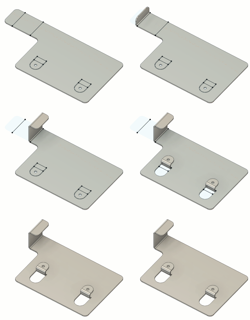
Bend sheet metal bodies
Learn how to use the Bend tool to create bends on a sheet metal body in Fusion.
Before you can bend a sheet metal body, create a sketch on the face of the sheet metal flange and position a straight sketch line for each bend.
On the Sheet Metal tab, select Create > Bend
 .
.The Bend dialog displays.
In the canvas, select a face to be the Stationary Side.
Select straight sketch lines that are planar to the Stationary Side to bend.
Note: The order of selecting the bend lines is important. To bend a sheet metal body across several lines, start with the lines farthest from the stationary side.Specify the Bend Angle relative to the stationary side.
The angle cannot be 0 and must be greater than -180 or less than 180 degrees.
Optional: In the Bend dialog, adjust the options and associated settings for each bend:
- Flip
 : Flips the direction of the bend.
 - Bend Line Position
 : Specifies the location of the bend.
- Start
 : Starts the bend at the sketch line.
 - Center
 : Centers the bend on the sketch line.
 - End
 : Ends the bend at the sketch line.
- Start
- Bend Relief:
- On: Automatically applies a bend relief where necessary. If Bend Relief is turned on, you can use the Override Rules to create different bend relief shapes.
- Off: Disables bend reliefs for the bend.
- Flip
Optional: In the Bend dialog, adjust settings:
- Corner Relief: Check to automatically apply a corner relief where necessary. Uncheck for no corner reliefs.
- Override Rules: Check to override the the bend, bend relief and corner relief options.
Click OK.
The sheet metal body with specified bends displays in the canvas.
