Flange reference
The Flange tool creates a sheet metal base flange, contour flange, edge flange, or lofted flange based on profiles you select in Fusion.
Design > Sheet Metal > Create > Flange ![]()
Type
 Edge Flange: Creates a sheet metal flange from a selected profile.
 Lofted Flange: Creates a sheet metal flange that connects two selected profiles.
Selection box (Edge Flange type)
Add or remove selection sets to apply different flange settings to each selection set.
Each line in the selection box represents a different flange profile.
Adjust the following for each row independently:
Selection Set
Flange Width Type
 Full Edge: Creates a flange along the entire length of the selected edge.
 Symmetric: Creates a flange of a specific width centered on the mid-point of the selected edge.
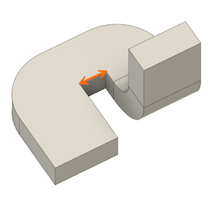
- Distance: Specify the overall distance of the flange, centered on the edge.
 Two Sides: Creates a flange of a specified width with the center of the selected edge but two possible distances to both sides.
- Distance 1: Specify the distance from the center of the flange edge to one side.
- Distance 2: Specify the distance from the center of the flange edge to one side.

 Two Offsets: Creates a flange to two selected offsets.
- Reference 1: Select a reference object to offset the edge of the flange from.
- Offset 1: Specify the distance to offset the edge of the flange from its reference.
- Reference 2: Select a reference object to offset the edge of the flange from.
- Offset 2: Specify the distance to offset the edge of the flange from its reference.
+: Add a selection set to the list.
X: Remove the highlighted selection set from the list.
Edges/Profiles (Edge Flange type)
Select sheet metal edges or sketch geometry to use for base flange, edge flange, or contour flange profiles.
- Select a closed sketch profile to create a base flange.
- Select sheet metal edges to create edge flanges.
- Select an open sketch profile to create a contour flange.
- Select a sheet metal edge and an open sketch profile on a plane that is normal to the sheet metal edge to join a contour flange to an existing flange.
Profiles (Lofted Flange type)
Select two open or two closed sketch profiles to use for lofted flange profiles.
Tangent Chain
Check to automatically select connected chains of geometry.
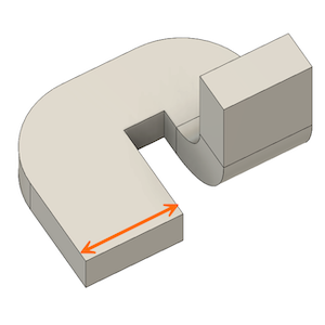
Distance (Edge Flange type)
Specify the distance to extrude the selected profile to one or both sides, based on the Direction setting.
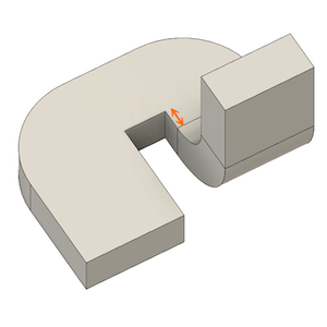
Height (Edge Flange type)
Specify the distance to extrude the flange from the height datum.
Angle (Edge Flange type)
Specify the angle of the flange relative to the selected edges on the base flange.
Height Datum (Edge Flange type)
Controls where the flange height is measured from.
 Inner Faces: Measures the flange height from the intersection of the inner faces of the base flange and the new flange.
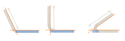
 Outer Faces: Measures the flange height from the intersection of the outer faces of the base flange and the new flange.
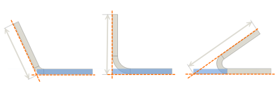
 Tangent To Bend: Measures the flange height tangent to the bend between the base flange and new flange, parallel to the new flange.
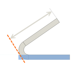
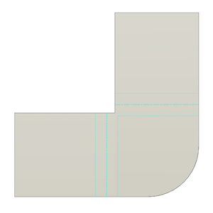
Bend Position (Edge Flange type)
Controls where the bend is positioned between the base flange and the new flange.
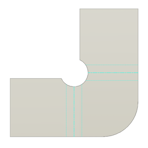
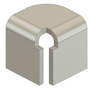
 Inside: Positions the bend inside the boundary of the outermost faces of the base flange and new flange.
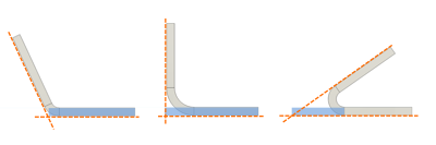
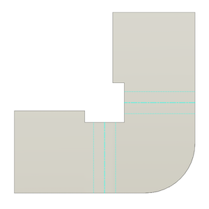
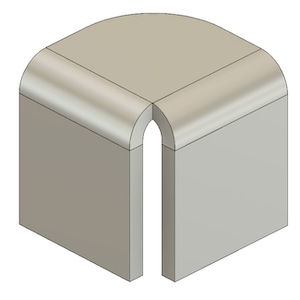
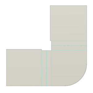
 Outside: Positions the bend outside the boundary of the innermost faces of the base flange and new flange.
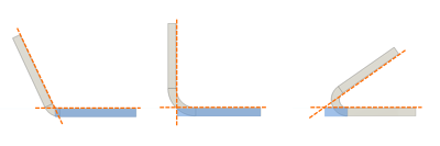
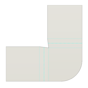
 Adjacent: Positions the bend so that it starts at the selected edge on the base flange.
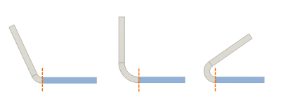
 Tangent: Positions the bend so that it is tangent to the selected edge on the base flange.
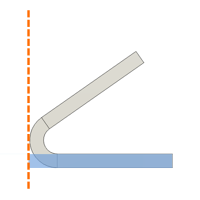
Flip (Edge Flange type)
![]() Flips the new flange 180 degrees over the base flange.
Flips the new flange 180 degrees over the base flange.
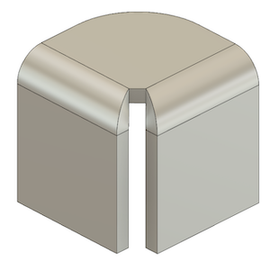
Miter Corners (Edge Flange type)
Miters the corners where sheet metal corners would otherwise overlap.
Orientation
Orients the sheet metal material relative to the selected sketch profile.
 Side 1: Offsets the sheet metal material to one side of the profile.
 Side 2: Offsets the sheet metal material to one side of the profile.
 Center: Centers the sheet metal material on the profile.
Direction (Edge Flange type)
Controls the direction that sheet metal flange is extruded from the sketch profile.
 One Side: Creates an extrusion on one side of the profile plane.
 Two Sides: Creates a unique extrusion on each side of the profile plane.
 Symmetric: Creates identical extrusions on each side of the profile plane.
Forming Type (Lofted Flange type)
Declares the intended manufacturing method for the lofted sheet metal body.
 Brake Form: Creates sheet metal flanges that will be formed using a press brake with a punch and die as the manufacturing method.
 Die Form: Creates sheet metal flanges that will be formed using a stamping die as the manufacturing method.
Facet Control (Lofted Flange type)
Controls the facets that create the bends in the lofted sheet metal body.
 Chord Tolerance: Lets you specify the maximum distance from an arc segment to the chord that spans between its end points to determine the number of facets to create around the bend.
 Facet Angle: Lets you specify the maximum angle between the end points of each facet to determine the number of facets to create around the bend.
 Facet Distance: Lets you specify the maximum distance between the end points of each facet to determine the number of facets to create around the bend.
 Facet Number: Lets you specify the number of facets to create around the bend.
Operation
Select an operation to control how the feature affects the design.
 New Body: Creates a new body in the active component.
 New Component: Creates a new body in a new component.
Sheet Metal Rule
Displays the list rules available in the design when the component does not yet have a Sheet Metal Rule assigned.
Select a rule from the list to assign it to the component when the flange is created.
Override Rules
Lets you override specific setting values for the new flange.
Check to apply overrides. Uncheck to restore all setting values to those defined in the Sheet Metal Rule.
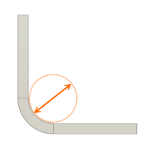
Bend Override
Lets you override the bend radius value for the new flange.
Check to apply overrides. Uncheck to restore the value defined in the Sheet Metal Rule.
- Bend Radius: Specify the bend radius value to override the sheet metal rule.
Bend Relief Override
Lets you override the relief shape, width, depth, and remnant values of bends for the new flange.
Check to apply overrides. Uncheck to restore the values defined in the Sheet Metal Rule.
Relief Shape
Straight: Creates a bend relief with a squared notch and a width, depth, and remnant that you specify.

Tear: Creates no bend relief, so the material is torn and leaves a remnant that you specify.
Round: Creates a bend relief with a rounded notch and a width, depth, and remnant that you specify.
Relief Width: Specify the relief width value to override the sheet metal rule.
Relief Depth: Specify the relief depth value to override the sheet metal rule.
Relief Remnant: Specify the relief remnant value to override the sheet metal rule.
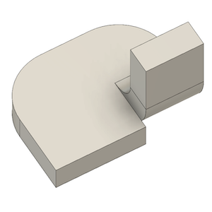
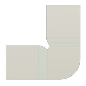
2 Bend Corner Override
Lets you override the relief shape, size, and placement at corners where 2 bends intersect.
Check to apply overrides. Uncheck to restore the values defined in the Sheet Metal Rule.
Relief Shape
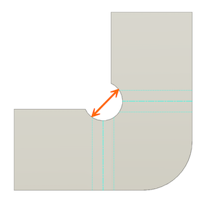
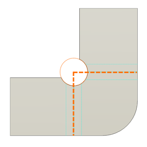
Round: Creates a bend relief in the shape of a circle, at a size and placement that you specify, centered on the corner where 2 bends meet.
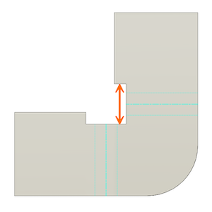
Square: Creates a bend relief in the shape of a square, at a size that you specify, centered on the corner where 2 bends meet.
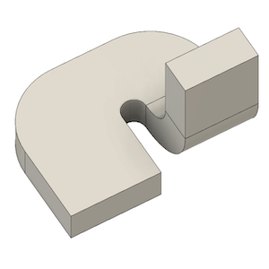
Tear: Creates no bend relief, so the material is torn at the corner where 2 bends meet.
Trim To Bend: Creates a bend relief in the shape of a square, defined by the limits of the bend zone, centered on the corner where 2 bends meet.

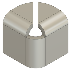
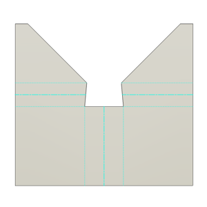
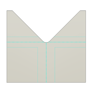
Linear Weld: Creates a bend relief in the shape of a V, cut from the corner of the bend zone on the base flange to the intersection of the bend zone on the edges of 2 flanges.

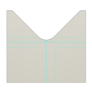
Arc Weld: Creates a bend relief in the shape of two splines, cut from intersection of the bend zone and the edges of two flanges to the points where they intersect the bend zone on the base flange, separated by the Miter/Rip/Seam Gap value.
Relief Size: Specify the relief size value to override the sheet metal rule. This dimension is measured when the sheet metal body is unfolded.
Round: The size of a round corner relief is the radius of the cutout.
Square: The size of a square corner relief is width of the square cut out.
Relief Placement
Tangent: Places a rounded relief shape so that it is tangent to the edges of 2 flanges where they meet the base flange.
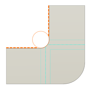
Intersection: Centers the relief shape on the intersection where 2 flanges meet the base flange.
3 Bend Corner Override
Lets you override the relief shape and radius at corners where 3 bends intersect.
Check to apply overrides. Uncheck to restore the values defined in the Sheet Metal Rule.
Relief Shape
No Replacement: Creates no special bend relief shape at the corner where 3 bends meet.
Intersection: Creates a bend relief shape by extending the flange edges until they intersect.

Full Round: Creates a bend relief shape by extending the flange edges until they intersect, then adding a full round fillet at the intersection, tangent to the flange edges starting at the bend zone.
Round With Radius: Creates a bend relief shape by extending the flange edges until they intersect, then adding a fillet of a size that you specify to round the intersection.
Relief Radius: Specify the relief radius value to override the sheet metal rule.