Precautions
Choose the appropriate type of analysis for the phenomena you are trying to simulate. To help you choose a simulation, read the brief descriptions on the Simulation Types page. Then, for more detailed information, follow the links provided on that page to see the individual analysis type topics.
Important:
- The accuracy of your simulation results is only as good as the assumptions you make when setting up the model.
- There is often more than one way to achieve the desired results. Favor the path that is the most efficient (minimizing model size and computing time) as long as the results are not compromised.
- Be careful not to overconstrain or underconstrain your model. Be sure that the model can move in the same way as the actual part or assembly it represents.
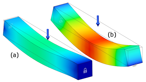
Example: If you want a solid model of a beam to behave as if it were simply supported, do not constrain the end faces. If the end face cannot translate axially, the beam is not free to rotate. Instead, apply the constraint to a single edge. This edge then acts as a fulcrum. The following image demonstrates the right and wrong way to simply support a square bar:

Figure 1: Comparison of Two Constraint Schemes.
(a:) Translation of the face at the right end is constrained in all three global directions. The end of the bar cannot rotate due to the axial constraint. Therefore, bar (a) behaves like a built-in beam, and it deflects much less than bar (b).
(b): Translation of the bottom edge at the right end is constrained in all three global directions. The bar is free to pivot on this edge. Therefore, bar (b) behaves as a simply supported beam, and it deflects much more than bar (a).
So, as you can see, you do not have to apply a rotational constraint to constrain rotation. In fact, rotational degrees of freedom (DOFs) are not applicable to solid elements. Therefore, rotational DOF constraints and moment loads applied to solid elements have no effect on the results. Ensure that your translational constraints do not impose an unintended and invalid rotational constraint.